Toolholder with detachable blade

Inactive Publication Date: 2001-02-13
KENNAMETAL INC
View PDF28 Cites 86 Cited by
  • Summary
  • Abstract
  • Description
  • Claims
  • Application Information

AI Technical Summary

Problems solved by technology

Because of this low thickness, the toolholder may be relatively fragile and any unexpected forces upon the toolholder may be sufficient to damage the toolholder.
When a portion of the toolholder supporting the cutting insert is an integral part of the toolholder, and when the toolholder is damaged and must be replaced, the entire toolholder must be replaced.
This is expensive and inconvenient even when the toolholder is a relatively simple and conventional square shank

Method used


Image

  • Toolholder with detachable blade
  • Toolholder with detachable blade
  • Toolholder with detachable blade

Examples


Embodiment Construction

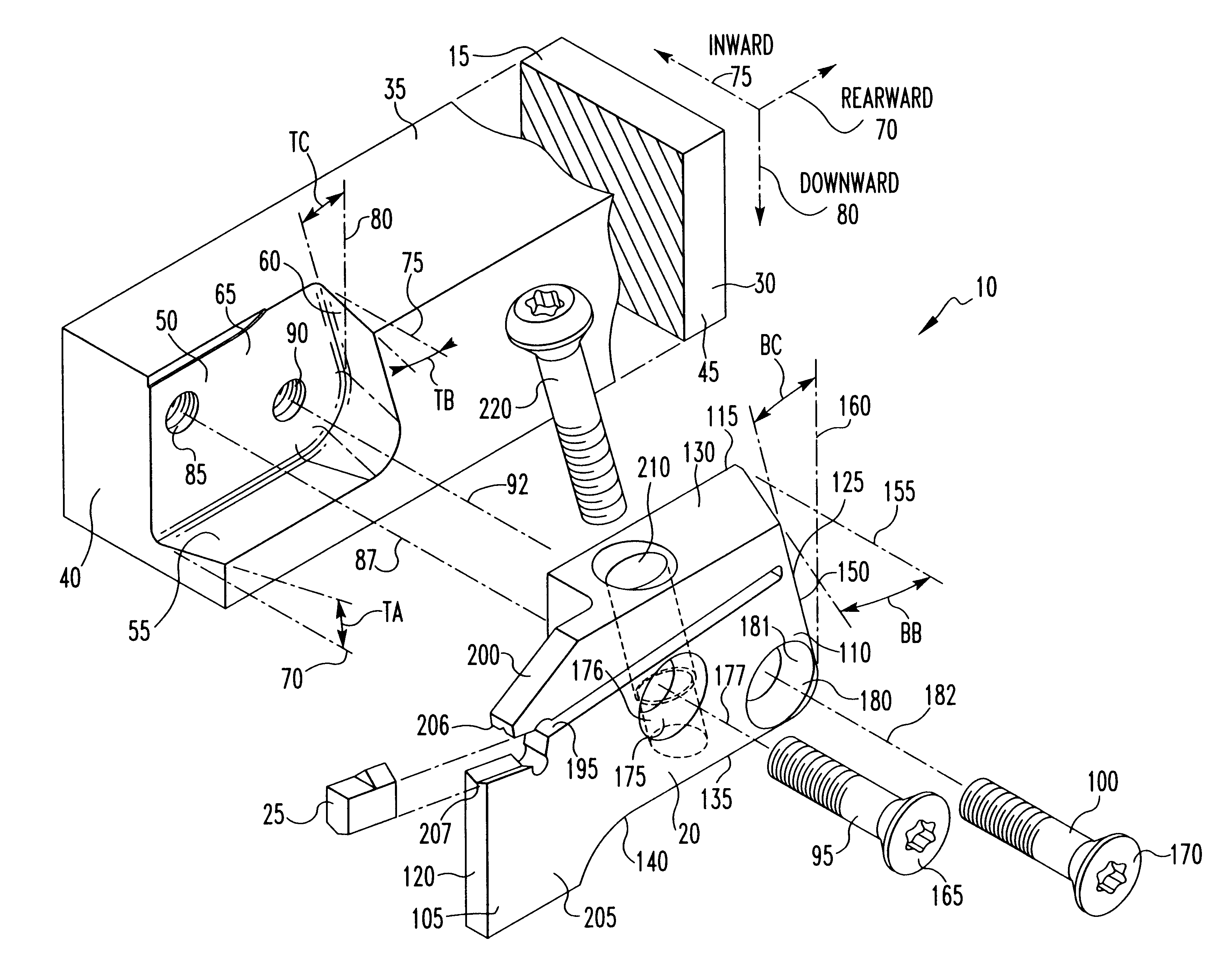
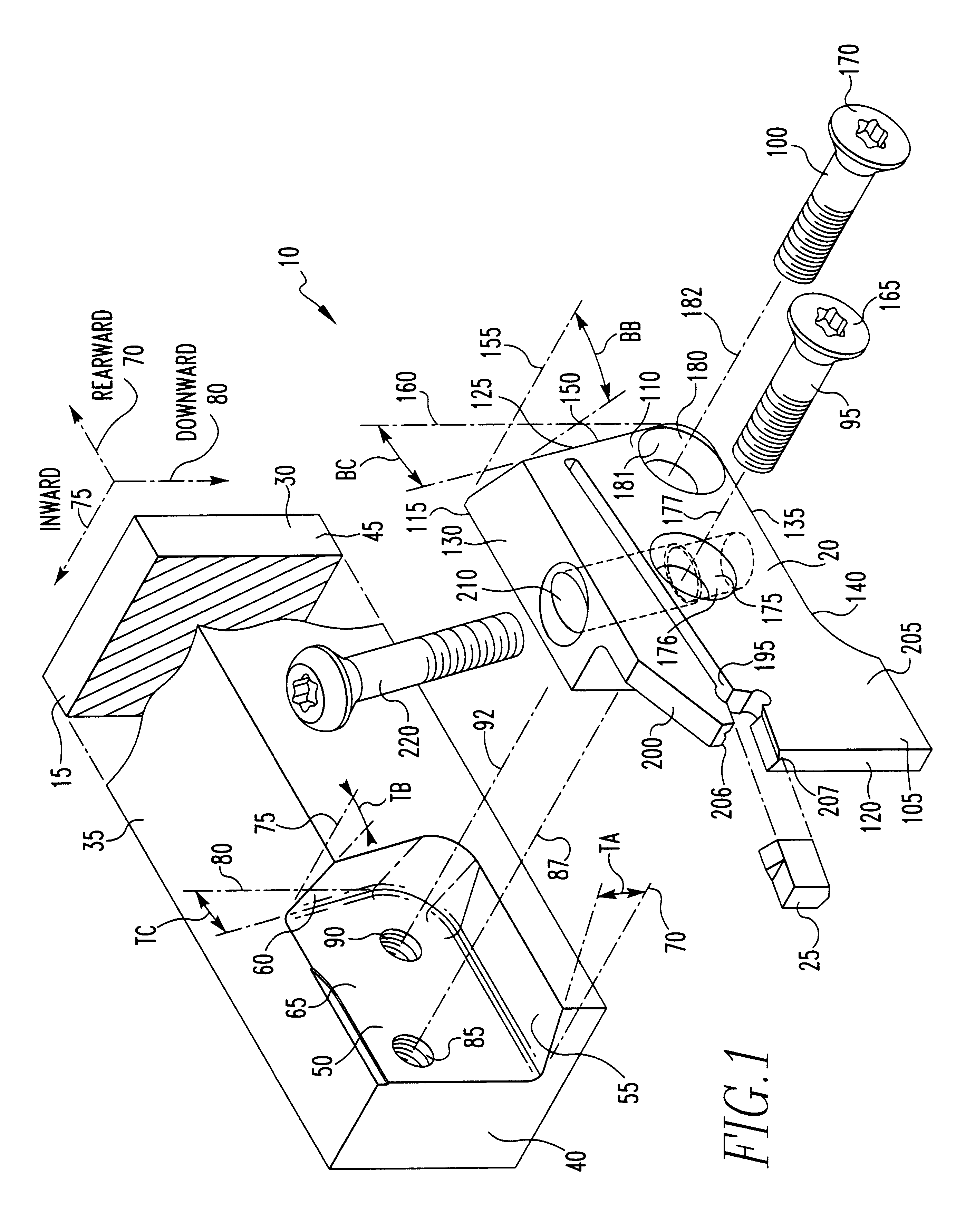
FIG. 1 illustrates an exploded isometric view of the toolholder assembly 10 in accordance with the subject invention. The toolholder assembly 10 is comprised of a toolholder 15 and removable blade 20. Within the removable blade 20, a cutting insert 25 suitable for metalworking applications is mounted.

The insert 25 in FIG. 1 is for illustrative purposes only and it should be understood the subject invention, which is directed toward the toolholder 15 and blade 20, may accommodate any of a large variety of inserts that may be suitable for a blade-type toolholder by, if necessary, modifying the details of the blade used to hold the insert, such as jaws designated by reference numbers 206 and 207.

The toolholder 15 is comprised of a toolholder body 30 having a toolholder top face 35, a toolholder end face 40 and a toolholder side face 45.

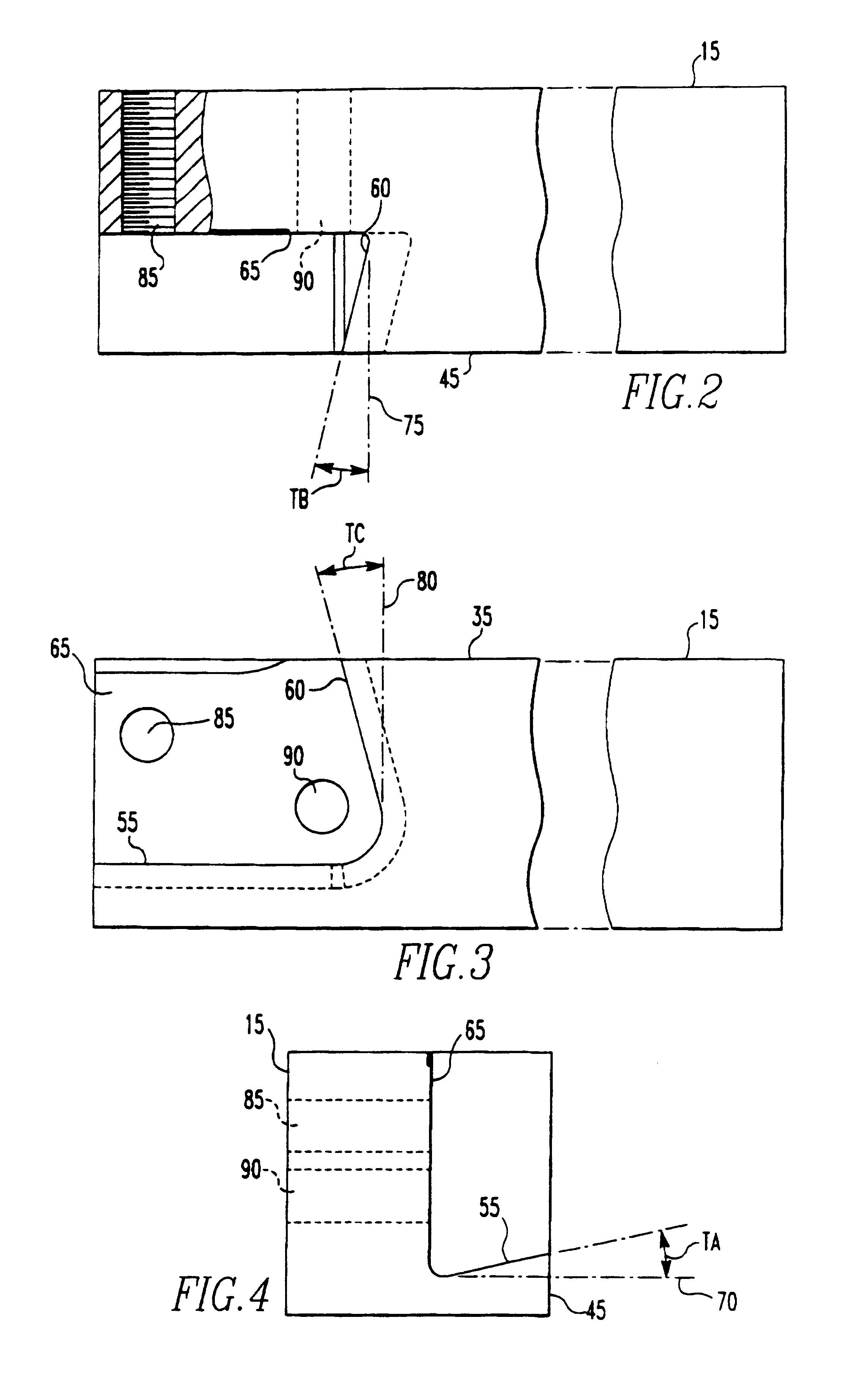
A pocket 50 extends into the toolholder body 30 and defines therein a pocket bottom wall 55, a pocket end wall 60 and pocket side wall 65. The pocket si...


PUM

PropertyMeasurementUnit
Angleaaaaaaaaaa
Angleaaaaaaaaaa
Widthaaaaaaaaaa

Abstract

A toolholder assembly for holding a cutting insert has a removable blade for mounting the cutting insert and a toolholder body for mounting the removable blade. The removable blade fits within a pocket in the toolholder body having angled sides to positively capture the blade.

Description

1. Field of the InventionThe invention is directed to a toolholder for cutting inserts used for metalworking operations and, more specifically, a blade which secures a cutting insert and is removably attached to the toolholder.2. Description of the Related ArtDuring a metalworking operation in which a cutting insert is used to produce a slot for grooving or for cutting off a workpiece, the thickness of the slot imparted by the cutting insert dictates the thickness of the toolholder supporting the cutting insert. As an example, if a cutting insert must penetrate a workpiece to a depth of two inches in order to perform a cutting operation, then at least two inches of the toolholder must also extend within the slot created by the machining operation. It is not unusual to create a groove having a thickness of less than one-sixteenth inch and, as a result, the associated portion of the toolholder must be slightly less than one-sixteenth inch to clear the machined slot. Because of this lo...

Claims


Application Information

Patent Timeline
IPC IPC(8): B23B27/04B23B27/00B23B29/00B23B29/04
CPCB23B27/04B23B29/043B23B2205/02Y10T407/25Y10T407/2286Y10T407/227Y10T407/2282B23B29/04
Inventor HALE, JOHN G.
Owner KENNAMETAL INC
Why Eureka
Try Eureka