Bow-mounted apparatus for detection and quantification of deviations in dynamic arrow position

a dynamic arrow and apparatus technology, applied in the direction of digital computer details, instruments, devices using time traversal, etc., can solve the problems of inaccurate methods, changes in shot dynamics, and inability to deliver actual bow system performan

Inactive Publication Date: 2001-02-20
DILGER JOHN PATRICK
View PDF3 Cites 50 Cited by
  • Summary
  • Abstract
  • Description
  • Claims
  • Application Information

AI Technical Summary

Problems solved by technology

With consideration to determining archery tackle performance, this method is inaccurate since the falling target must be released at the precise moment the arrow is loosed from the bow.
Any attempt to couple an electromechanical triggering device to the bow limb changes shot dynamics and will not deliver actual bow system performance.
Additionally, critical data with respect to arrow motion or position at the moment of arrow release has dissipated significantly if the measurement apparatus is not intimately coupled to the bow.
As with the first technique, arrow velocity can only be conveniently measured when the arrow is released with the measuring device placed in front of the bow system, thereby eliminating collection of critical data pertaining to initial arrow motion or position.

Method used


Image

  • Bow-mounted apparatus for detection and quantification of deviations in dynamic arrow position
  • Bow-mounted apparatus for detection and quantification of deviations in dynamic arrow position
  • Bow-mounted apparatus for detection and quantification of deviations in dynamic arrow position

Examples


Embodiment Construction

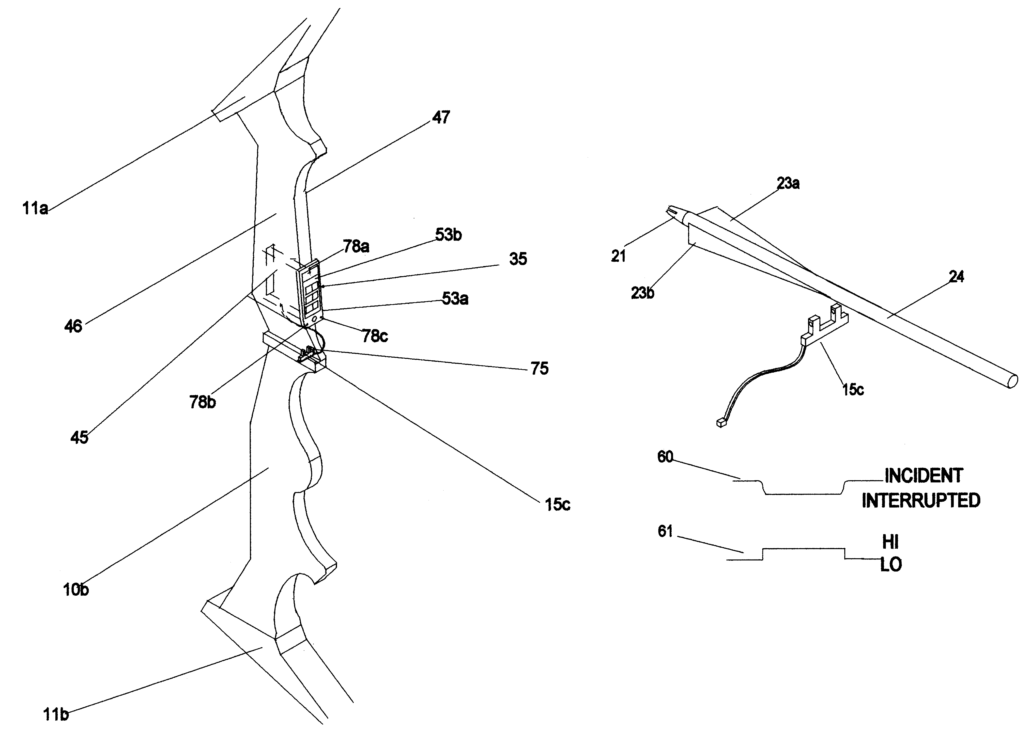
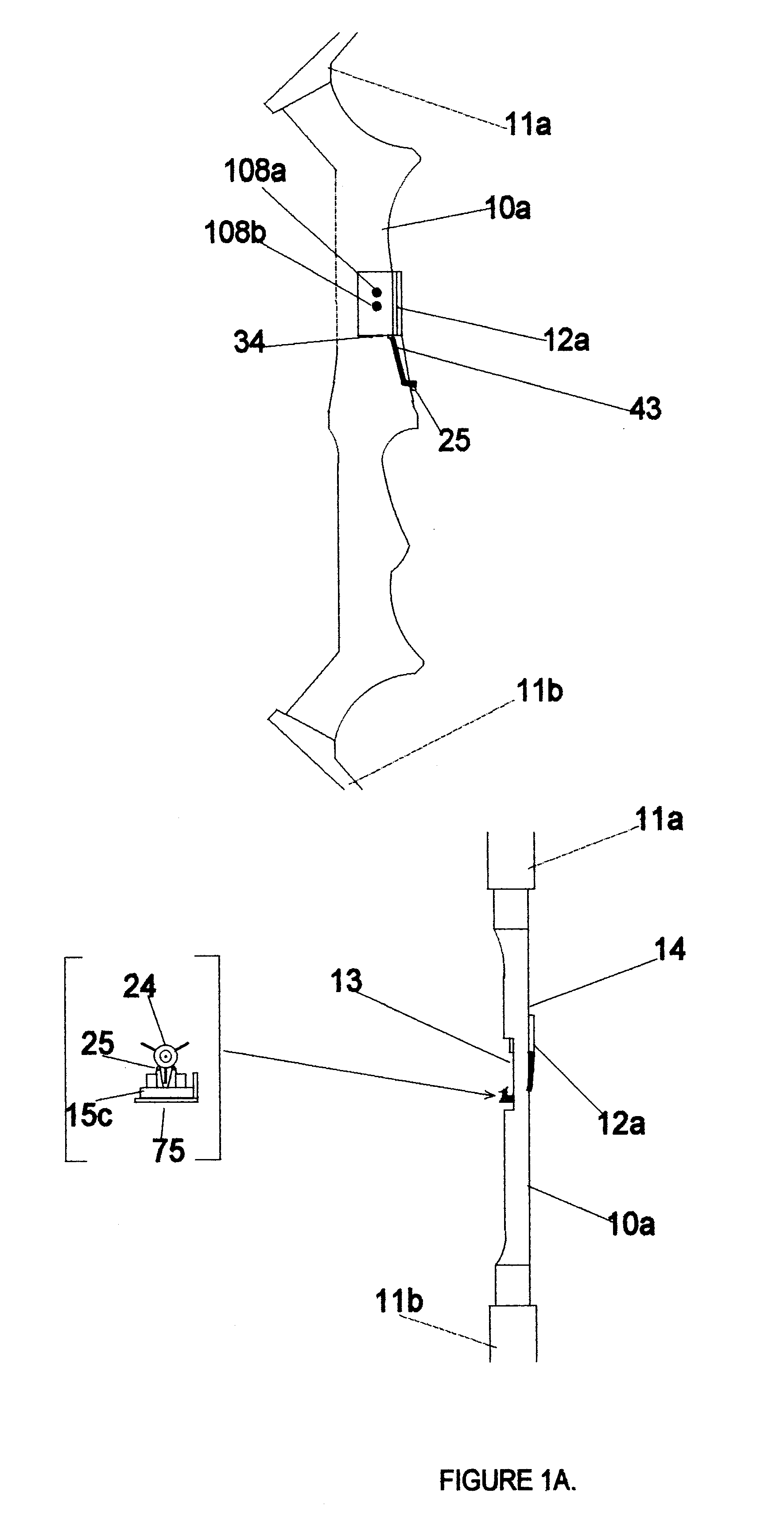
A perspective view of a bow-mounted measurement unit is illustrated in FIG. 3. The bow-mounted measurement unit is a battery-powered electronic circuit that is designed to be mounted external to a bow riser. The measurement unit displays statistical parameters such as consecutive data, mean, maximum, and minimum arrow position through a user-selectable interface.

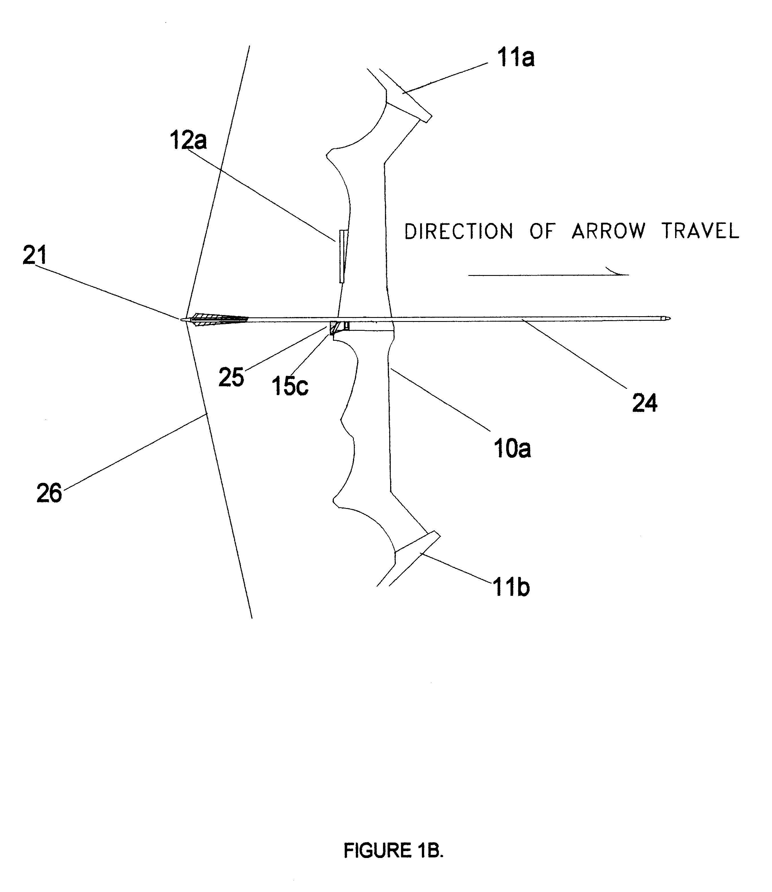
All structural features are illustrated in FIG. 3. Bow-mounted measurement unit 12a is comprised of an injection molded plastic housing assembly 57, a bezel 53a, a display lens 53b and a electronics assembly 35. Bow-mounted measurement unit 12a also includes a optical sensor 15c that is responsive to the interruption of a path of radiant flux. Optical sensor 15c is comprised of a single emitter-detector pair indirect opposition such as the commercially available OMRON EE-SPY461. A sensor cable-connector assembly 43 connects a voltage source 42 to optical sensor 15c. Optical sensor 15c output is connected to bow-mounted measu...


PUM


Abstract

An apparatus for quantifying the position of a released arrow as it passes across the bow riser. A low power, electronics measurement unit attached onto or mounted internal to a bow in communication with a sensor detects a signal from an arrow shaft for the purposes of collecting data pertaining to arrow position. The electronics measurement unit provides a user configurable gain to control the variation and sensitivity of the collected data. The optical trigger mechanism used to stimulate the sensor does not require arrow shaft modification. Statistical parameters of the collected data are displayed on the bow and are used to determine and improve archery tackle performance.

Description

This invention relates to archery equipment, specifically to an improved method of detecting and quantifying deviations in dynamic arrow position on a bow riser.In general, the archer and the archery tackle, that is the bow, arrow, release mechanism, arrow rest, and bow sight, are viewed as a bow system. With respect to archery physics, bow system consistency is the fundamental component in highly accurate shooting. Measuring arrow dynamics in the bow system is a superior way to detect and improve performance. As those skilled in the art are filly aware, minute deviations in archery tackle setup or variations in hand position during arrow release degrade bow system accuracy. When an arrow is released from the bow system, vertical and horizontal bending moments are always induced in the arrow shaft. The trajectory of an arrow is dynamically stable and contains damped sinusoidal bending moments or oscillations in both vertical and horizontal planes along the longitudinal axis of the a...

Claims


Application Information

Patent Timeline
Patent Type & Authority Patents(United States)
IPC IPC(8): F41B5/00F41B5/14G01P3/64G01P3/66
CPCF41B5/14G01P3/66F41B5/1484
Inventor DILGER, JOHN PATRICK
Owner DILGER JOHN PATRICK
Why Eureka
Try Eureka