Intravascular self-anchoring electrode body with arcuate springs, spring loops, or arms

a self-anchoring, electrode body technology, applied in the direction of internal electrodes, transvascular endocardial electrodes, therapy, etc., can solve the problems of poor sub-threshold stimulation of the target area, affecting system efficiency, and stimulation of a non-targeted region of the brain, so as to minimize the occlusion of blood flow, facilitate the implantation of medical devices, and efficient transmission

Inactive Publication Date: 2007-06-12
BOSTON SCI SCIMED INC
View PDF144 Cites 181 Cited by
  • Summary
  • Abstract
  • Description
  • Claims
  • Application Information

AI Technical Summary

Benefits of technology

[0008]Thus, although the present inventions should not be so limited in their broadest aspects, the firm placement of the electrode(s) against the inner surface of the vessel wall by the action of the spring loops allows the electrical energy to be more efficiently transmitted to and / or received from the vessel wall and surrounding tissue, while minimizing the occlusion of blood flow. In addition, due to their placement on one side of the vessel wall, the electrode(s) focus the transmission of the electrical energy into and / or the reception of the electrical energy from a targeted tissue site.
[0012]Thus, although the present inventions should not be so limited in its broadest aspects, the firm placement of the electrode(s) against the inner surface of the vessel wall by the action of the spring arms allows the electrical energy to be more efficiently transmitted to and / or received from the vessel wall and surrounding tissue, while minimizing the occlusion of blood flow.
[0013]In accordance with a fifth aspect of the present inventions, an expandable intravascular medical device is provided. The medical device comprises an arcuate spring configured to be expanded into firm contact with the inner surface of a blood vessel. The arcuate spring is non-tubular, i.e., it spans less than 360 degrees. In one embodiment, the arcuate spring spans greater than 180 degree. This allows the arcuate spring to more easily anchor the medical device to the inner surface of a blood vessel when expanded.
[0016]Thus, although the present inventions should not be so limited in their broadest aspects, the firm placement of the electrode(s) against the inner surface of the vessel wall by the action of the arcuate spring allows the electrical energy to be more efficiently transmitted to and / or received from the vessel wall and surrounding tissue, while minimizing the occlusion of blood flow. Also, the non-tubular nature of the arcuate spring allows the medical device to adapt to various sizes of blood vessels as compared to tubular structures. In addition, due to the non-tubular nature of the arcuate spring, the electrode(s) can be more easily configured to focus the transmission of the electrical energy into and / or the reception of the electrical energy from a targeted tissue site.
[0019]Thus, although the present inventions should not be so limited in its broadest aspects, the existence of the inner insulative surface of the arcuate structure electrically insulates the blood from electrical energy transmitted and / or received by the electrode(s), while minimizing the occlusion of blood flow.

Problems solved by technology

Invariably, this may potentially cause poor sub-threshold stimulation of the target area, or worse, stimulation of a non-targeted region of the brain.
Increasing the gain can also impact the system efficiency by reducing the battery life of the implanted stimulation source.

Method used


Image

  • Intravascular self-anchoring electrode body with arcuate springs, spring loops, or arms
  • Intravascular self-anchoring electrode body with arcuate springs, spring loops, or arms
  • Intravascular self-anchoring electrode body with arcuate springs, spring loops, or arms

Examples


Embodiment Construction

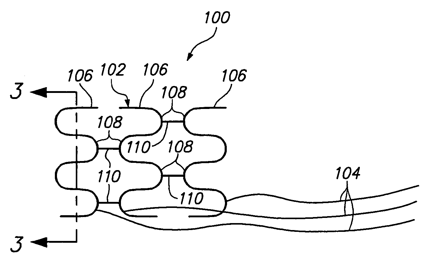
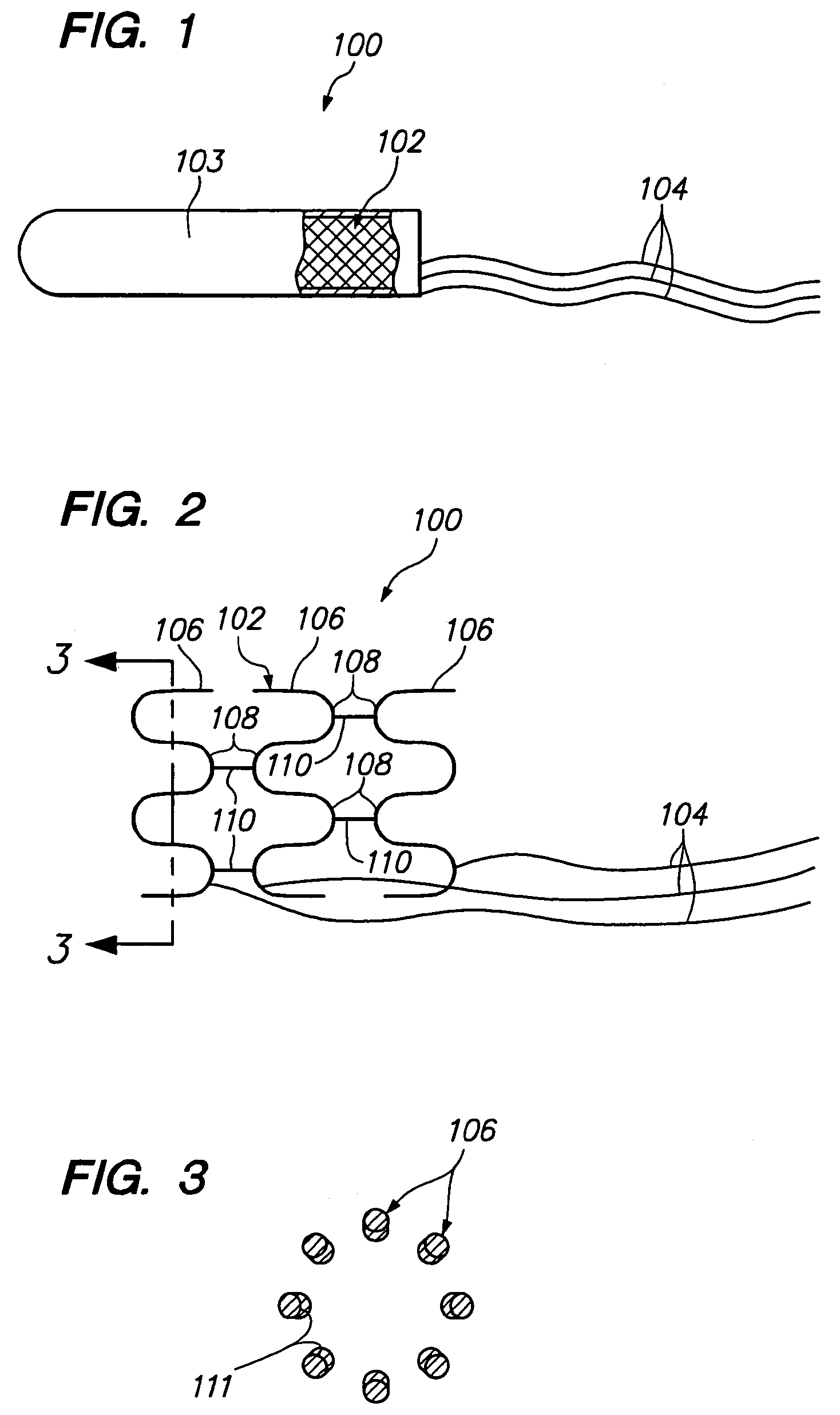
[0055]Referring now to FIGS. 1–3, an intravascular medical device 100 constructed in accordance with a preferred embodiment of the present inventions will be described. The medical device 100 comprises an expandable / collapsible tubular electrode body 102, and a plurality of flexible conductive leads 104 electrically coupled to the electrode body 102. For the tubular body can either be continuous tubular structure or a structure that has a tubular profile, such as a coil. The electrode body 102 can be transformed from a collapsed geometry (FIG. 1) into an expanded geometry (FIG. 2). In its collapsed geometry, the medical device 100 can be intravascularly delivered to a target site within a vessel using a standard stent delivery apparatus. In order to maintain the medical device 100 in its collapsed geometry, a removable sheath or covering 103 is disposed over the collapsed electrode body 102. The sheath 103 may have one or more delivery wires (not shown) that can be pulled in order t...


PUM


Abstract

An expandable intravascular medical device comprises an arcuate spring configured to be expanded into contact with the inner surface of a blood vessel. Another medical device comprises an electrode support structure, e.g., a non-tubular arcuate structure or a cylindrical member, and a plurality of resilient spring loops laterally extending from the support structure. The contact created between the loops and a blood vessel is sufficient to anchor the medical device within the blood vessel. In another embodiment, the medical device comprises an elongated member and two resilient spring arms extending distally from the elongated member. The arms are configured to be laterally moved towards each other to place the medical device in a collapsed geometry, and configured to be laterally moved away from each into contact with an inner surface of a blood vessel to place the medical device an expanded geometry.

Description

RELATED APPLICATIONS[0001]This application is related to copending U.S. patent application Ser. No. 10 / 841,069, filed on the same date, and expressly incorporated herein by reference.FIELD OF THE INVENTION[0002]The invention relates to the intravascular delivery of medical devices into a patient, and in particular, the intravascular implantation of stimulation and / or recording electrode leads into a patient.BACKGROUND OF THE INVENTION[0003]There are certain circumstances in which it is desired to electrically stimulate tissue and / or record electrical signals received from such tissue via blood vessels. For example, U.S. patent application Ser. No. 10 / 744,319, which is expressly incorporated herein by reference, describes a method of treating neurological disorders by intravenously delivering stimulation leads within the brain, thereby obviating the need to invasively create a burr hole in the cranium of the patient.[0004]Despite the minimally invasive benefits provided by these type...

Claims


Application Information

Patent Timeline
Patent Type & Authority Patents(United States)
IPC IPC(8): A61N1/00A61F2/89A61N1/05A61N1/378
CPCA61N1/057A61N1/3787A61N2001/0585
Inventor WALLACE, MICHAEL P.GARABEDIAN, ROBERT J.MANERS, WENDELIN C.ABRAMS, ROBERT
Owner BOSTON SCI SCIMED INC
Why Eureka
Try Eureka