Maximum support tlif implant

a technology of tlif implants and support beams, applied in the field of medical devices, can solve problems such as spinal stenosis, spinal canal narrowing, degenerative disc disease,

Active Publication Date: 2009-06-04
CUSTOM SPINE INC
View PDF5 Cites 167 Cited by
  • Summary
  • Abstract
  • Description
  • Claims
  • Application Information

AI Technical Summary

Benefits of technology

[0010]The first end of the second member further includes an arcuately-shaped attachment head corresponding to the arcuately-shaped cut out region of the first member. The attachment head comprises a receptor dimensioned and configured to pivotally attach to the hinge of the first member. A first lateral side of the attachment head is offset from an edge of the first lateral portion and a second lateral side of the attachment head is planar with an edge of the second lateral portion. A tip of the tapered configuration of the second end comprises a hole recess positioned parallel to a longitudinal axis of the second member. The first end comprises a hole recess adjacent to the attachment head and aligned with the hole recess of the second end.

Problems solved by technology

Due to aging and some injuries, the intevertebral discs start degenerating leading to degenerative disc disease.
This causes chronic back pain and can gradually lead to spinal stenosis in which the spinal canal becomes narrower and puts pressure on the spinal cord and nerves.
These devices however, do not offer significant change in direct endplate support.

Method used


Image

  • Maximum support tlif implant
  • Maximum support tlif implant
  • Maximum support tlif implant

Examples


Embodiment Construction

[0024]The embodiments herein and the various features and advantageous details thereof are explained more fully with reference to the non-limiting embodiments that are illustrated in the accompanying drawings and detailed in the following description. Descriptions of well-known components and processing techniques are omitted so as to not unnecessarily obscure the embodiments herein. The examples used herein are intended merely to facilitate an understanding of ways in which the embodiments herein may be practiced and to further enable those of skill in the art to practice the embodiments herein. Accordingly, the examples should not be construed as limiting the scope of the embodiments herein.

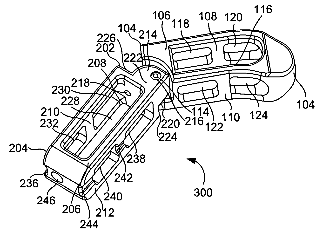
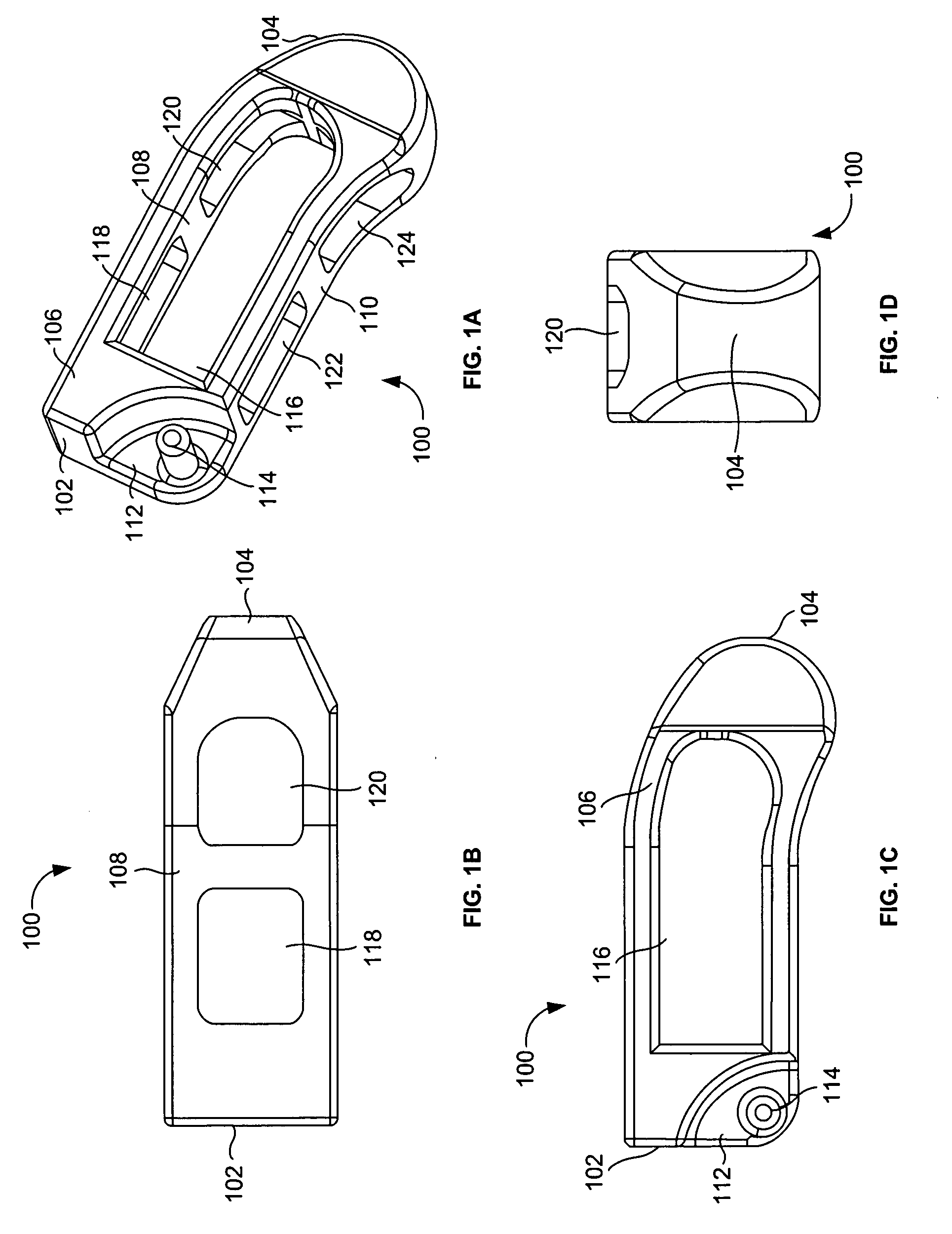
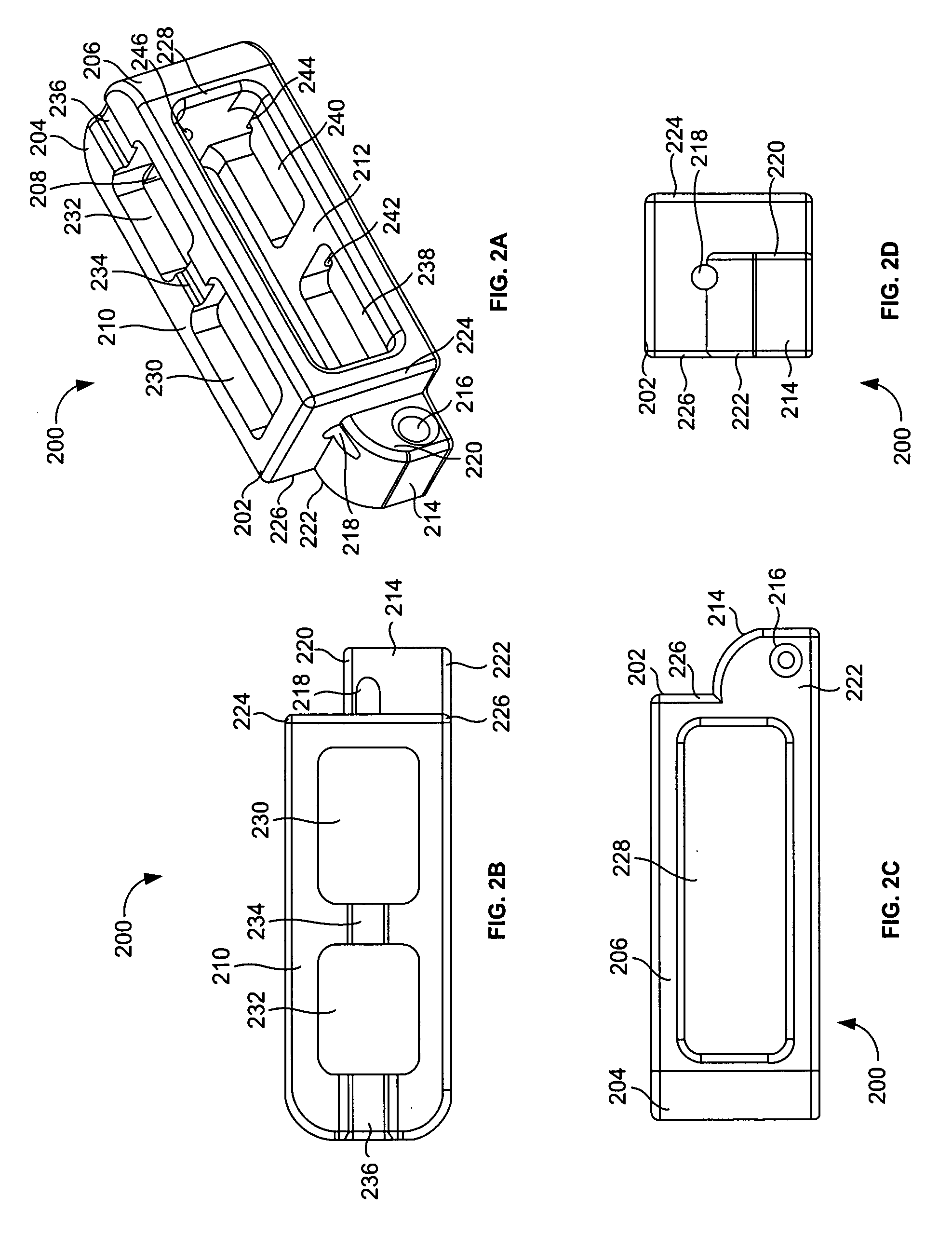
[0025]As mentioned, there remains a need for a new TLIF implant cage to provide maximum surface area with excellent pain control and improved stability. The embodiments herein achieve this by providing a TLIF implant to be placed in an intervertebral space, the TLIF implant including a front me...


PUM


Abstract

A transforaminal lumbar interbody fusion (TLIF) implant to be placed in an intervertebral space includes a front member and a back member. The front member includes a first end having a hinge, a second end, a pair of lateral portions, a top wall and a bottom wall, an opening configured through the pair of lateral portions and a plurality of openings in each of the top wall and the bottom wall. The back member includes a first end having an arcuately-shaped attachment head comprising a receptor dimensioned and configured to accommodate the hinge of the front member, a second end, a pair of lateral portions, a top wall, a bottom wall and an opening configured through the pair of lateral portions. The top wall and the bottom wall of the back member further comprise a plurality of openings.

Description

BACKGROUND[0001]1. Technical Field[0002]The embodiments herein generally relate to medical devices, and, more particularly, to a maximum support TLIF implant used during orthopedic surgeries.[0003]2. Description of the Related Art[0004]Intervertebral discs, which occupy one fourth of the human vertebral column's total length, are fibrocartilaginous cushions between two adjacent vertebrae. The discs act as shock absorbers and protect the vertebrae, brain, and nerves. The discs permit some limited vertebral extension and flexion motions as well as maintain the stability of the vertebral segments while absorbing external forces. Due to aging and some injuries, the intevertebral discs start degenerating leading to degenerative disc disease. This causes chronic back pain and can gradually lead to spinal stenosis in which the spinal canal becomes narrower and puts pressure on the spinal cord and nerves. Spinal fusions are common procedures used for fusing and stabilizing the vertebrae.[00...

Claims


Application Information

Patent Timeline
Patent Type & Authority Applications(United States)
IPC IPC(8): A61F2/44
CPCA61F2/4455A61F2/4611A61F2002/2835A61F2002/30112A61F2002/30471A61F2230/0004A61F2002/30784A61F2002/3082A61F2002/30904A61F2220/0091A61F2002/30579
Inventor MCCLELLAN, III, JOHN W.MCCLELLAN, MATTHEW P.
Owner CUSTOM SPINE INC
Why Eureka
Try Eureka