Method for mounting component

a technology for mounting components and components, applied in the direction of gripping heads, metal working apparatuses, manufacturing tools, etc., can solve the problems of difficulty in shortening the movement time any further, and preventing the achievement of higher speeds for component mounting

Inactive Publication Date: 2001-03-06
PANASONIC CORP
View PDF15 Cites 24 Cited by
  • Summary
  • Abstract
  • Description
  • Claims
  • Application Information

AI Technical Summary

Problems solved by technology

However, in recent years, even higher component mounting speed has been demanded, and in this case, whilst it is relatively simple to shorten the movement time of the mounting heads 12 by increasing the speed of rotation of the rotating table 11 in the mounting section 1, the time that can be used for moving the component supply table 9 and the XY table 4 is more restricted than the movement time for the mounting heads, and therefore it is difficult to shorten this movement time any further.
Therefore, whilst it is necessary to shorten the distance of movement of the component supply table 9 and the XY table 4 in order to increase the speed of component mounting, this is not possible with a conventional device construction, and therefore presents a major impediment to achi

Method used


Image

  • Method for mounting component
  • Method for mounting component
  • Method for mounting component

Examples


Embodiment Construction

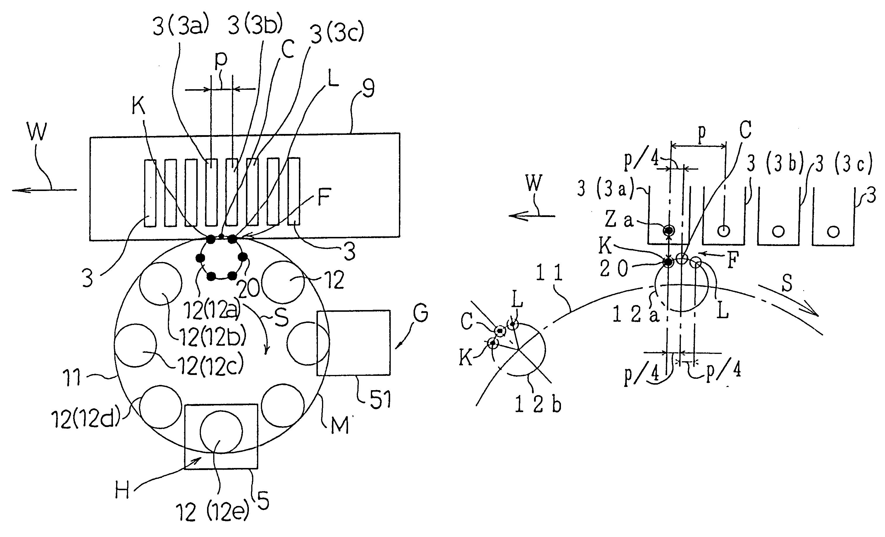
Below, the method and device for mounting electronic components according to the present invention is described with reference to FIG. 1-FIG. 4. The overall construction of the device for mounting electronic components is substantially the same as the prior art example described with reference to FIG. 7 and FIG. 8, and hence the description thereof is omitted here and only the characteristic features of the present embodiments are explained.

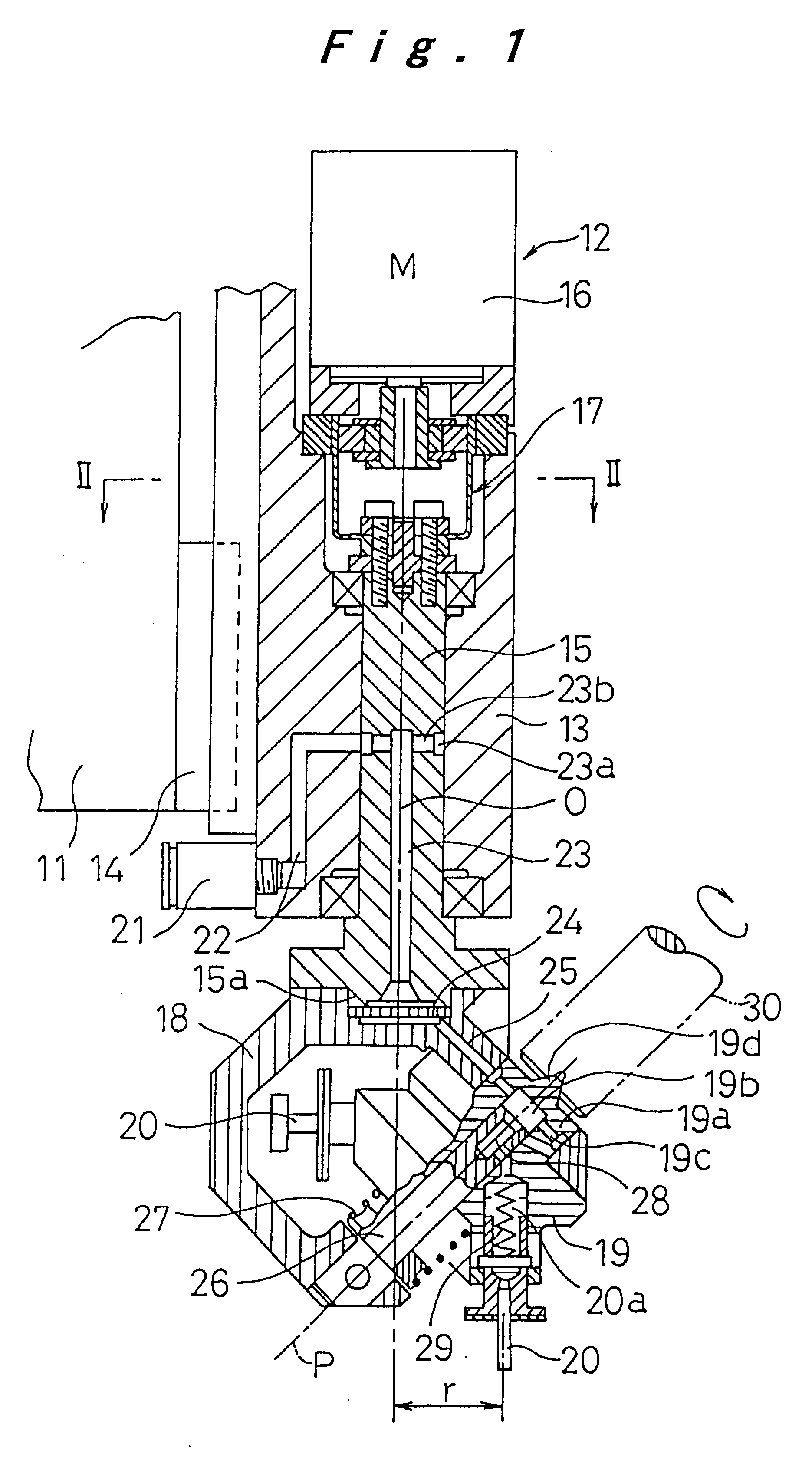
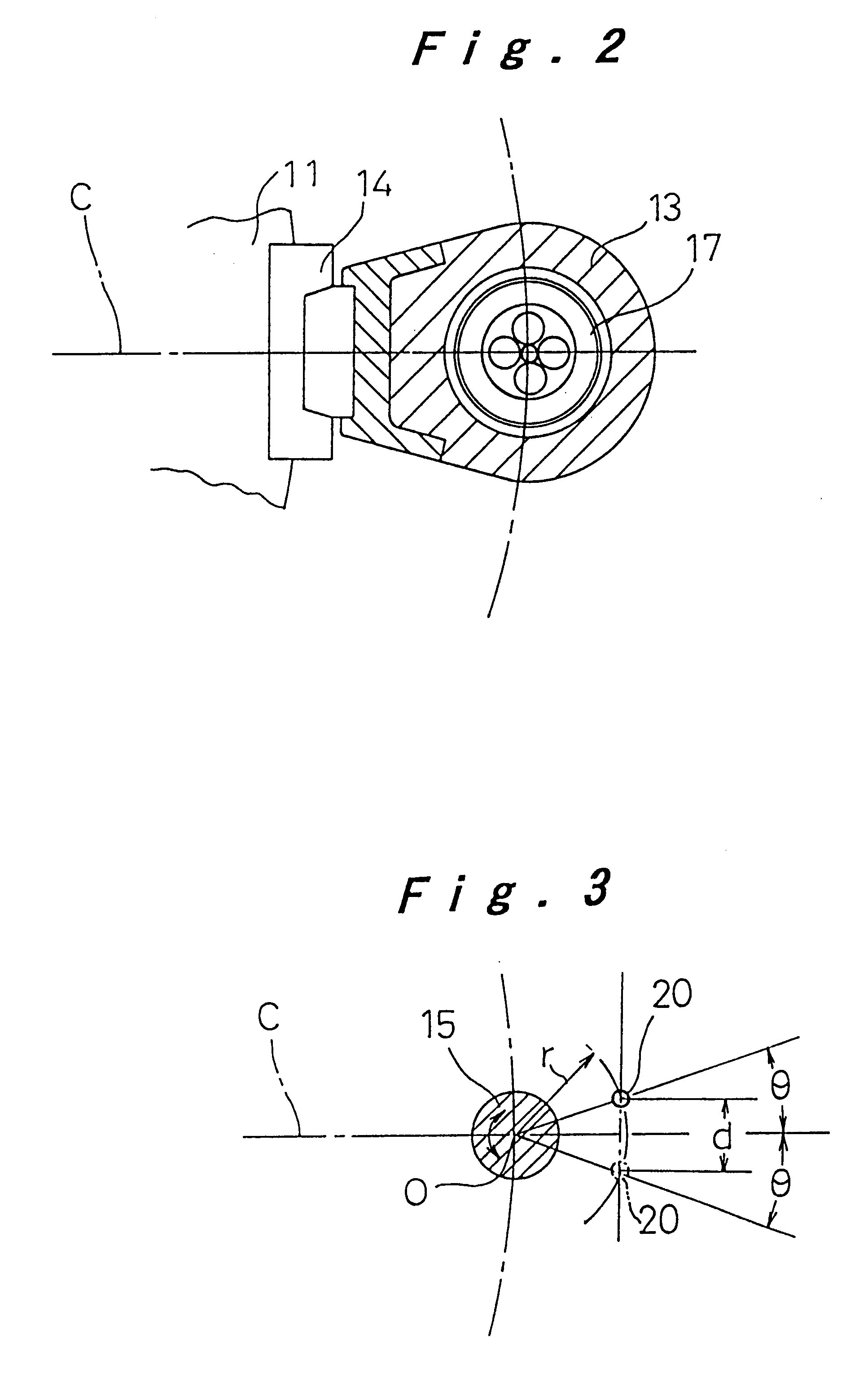
In FIG. 1 and FIG. 2, a plurality of mounting heads 12 are provided at regular intervals on the outer periphery of a rotating table 11 in a mounting section 1. Numeral 13 denotes the main section of a mounting head 12, which is held on the rotating table 11 such that it is movable in an upward and downward direction by means of a sliding guide 14, and a cam follower (not shown) which engages with a grooved cam (not shown) provided on the periphery of the rotating table 11 is mounted to the upper portion of this main section 13, such that the moun...


PUM

PropertyMeasurementUnit
Lengthaaaaaaaaaa
Lengthaaaaaaaaaa
Sizeaaaaaaaaaa

Abstract

A method for mounting components using mounting heads for which a plurality of suction or mounting operating positions are set for suction nozzles in a state where the mounting head is at rest in a component supply position or component mounting position, it being possible to select any of these operating positions, comprising a first step of selecting a component supply position or component mounting position such that the amount of movement of component feeder holding components to be mounted, or the amount of movement of the substrate to the mounting position for the next component to be mounted becomes a minimum, and moving the component feeder or substrate accordingly; and a second step of selecting a suction nozzle position corresponding to the component suction position or component mounting position in the first step, whilst the mounting head is moving towards the component suction position.

Description

1. Field of the InventionThe present invention relates to a method and device for mounting components whereby components such as electronic components, or the like, are mounted onto a substrate.2. Description of the Related ArtAs shown in FIG. 7, a conventional high-speed-type electronic component mounting device is generally constituted in such a manner that a component is extracted at a mounting section 1 from a desired component feeder 3 of a component supplying section 2, and the component is mounted automatically onto a substrate 5 set on an XY table 4. Numeral 6 denotes a transporting rail for transporting the substrate 5 to and from the device, and numeral 7 denotes a display section for displaying the operational state and any irregular states of the component mounting device.As shown in FIG. 8, in the component supplying section 2, a plurality of component feeders 3, into which component reels 8, wherein components are held on a tape and wound into a reel, are set, are moun...

Claims


Application Information

Patent Timeline
IPC IPC(8): H05K13/04B23P19/00B23P21/00B25J15/06
CPCH05K13/0452Y10S29/044Y10T29/4913Y10T29/49133Y10T29/53261Y10T29/49144Y10T29/53191Y10T29/53174Y10T29/53178H05K13/0417H05K13/041
Inventor HATA, KANJIOJI, SHIRONEGISHI, SHIGETOSHISENO, MAKITO
Owner PANASONIC CORP
Why Eureka
Try Eureka