Intramedullary nail

a technology of intramedullary nail and nail, which is applied in the field of intramedullary nail, can solve the problems of rigid fixation, difficult arthrodesis of ankle joint, and inability to pass through transfixation screws

Inactive Publication Date: 2001-03-06
FUJIMORI JUHRO +2
View PDF8 Cites 108 Cited by
  • Summary
  • Abstract
  • Description
  • Claims
  • Application Information

AI Technical Summary

Problems solved by technology

In this method, however, depending on the location of the fracture, there may be cases in which the transfixation screws do not pass through.
However, arthrodesis of the ankle joint is extremely difficult.
However, one problem that is common to these methods is that fixation is not rigid.
In particular, they do no sufficiently control rotation and bending of the ankle joint.
As a result, long period of immobilization without weight-bearing is required after surgery.
Furthermore, in cases where an external fixation device is used, the pin insertion areas tend to become contaminated, so that repeated dressings is required.
However, even if used in combination with transfixation screw, intramedullary nails do not sufficiently control rotation, pronation and supination, and dorsal and plantar flexion of the ankle-joint, particularly in patients with rheumatoid arthritis who have osteoporotic bone.

Method used


Image

  • Intramedullary nail
  • Intramedullary nail
  • Intramedullary nail

Examples


Embodiment Construction

A case in which the ankle joint is under arthrodesis using the intramedullary nail of the present invention will be described below with reference to the attached figures. FIG. 5 is a model diagram which shows the skeletal structure of the foot. The bones of the foot are connected in order, from the bottom, of the calcaneus 10, talus 12 and tibia 14. The articular surfaces of the calcaneus 10 and the talus 12, and the articular surfaces of the talus 12 and the tibia 14 form joints 16 and 18, respectively.

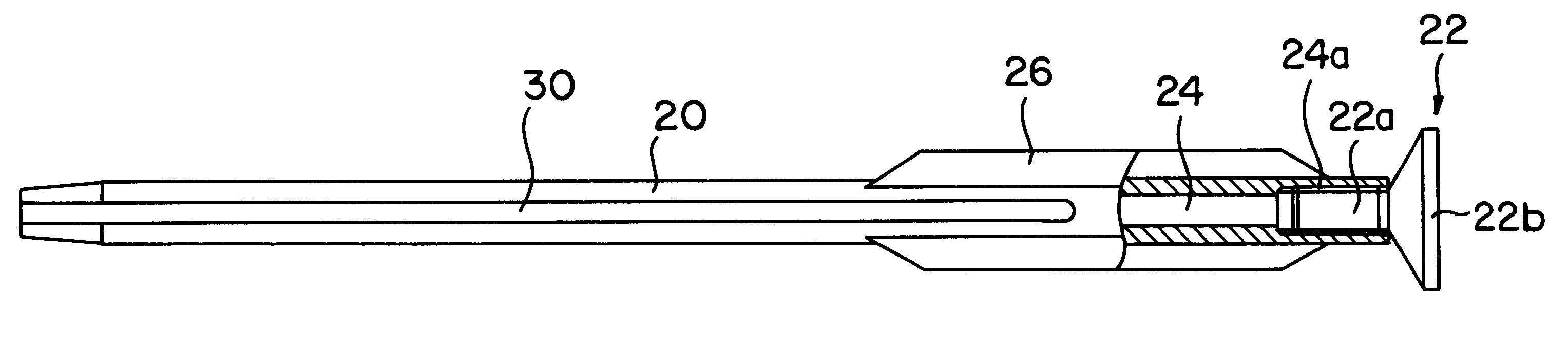
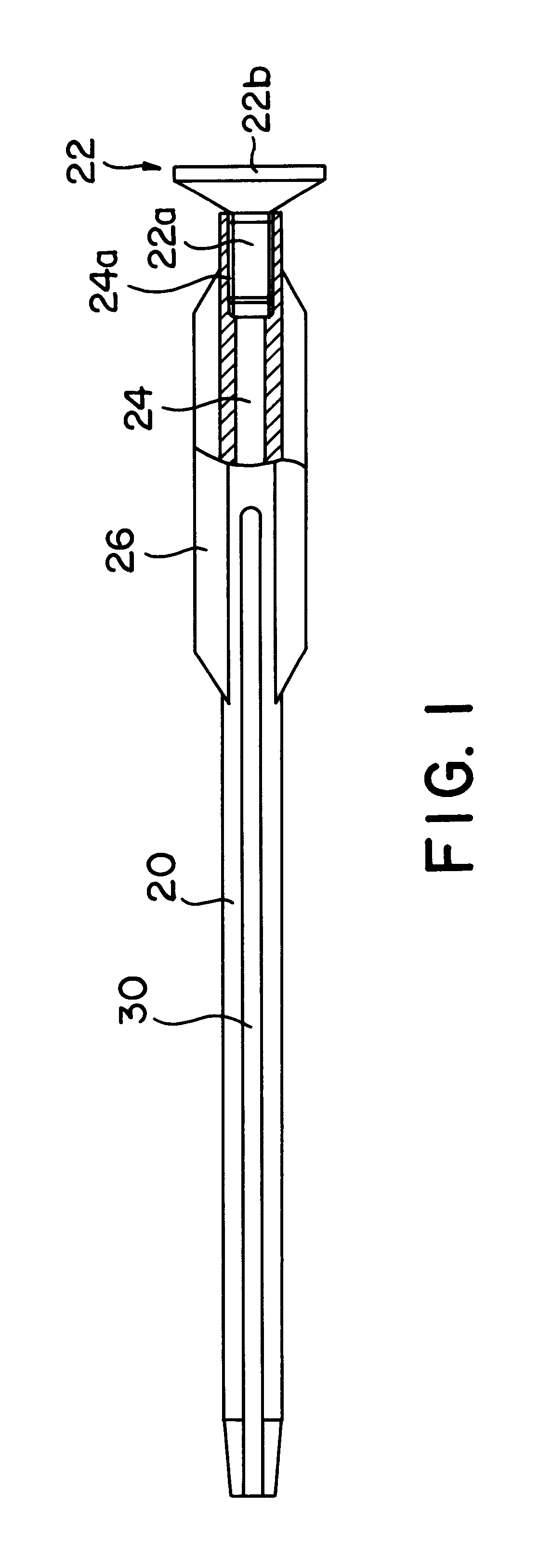
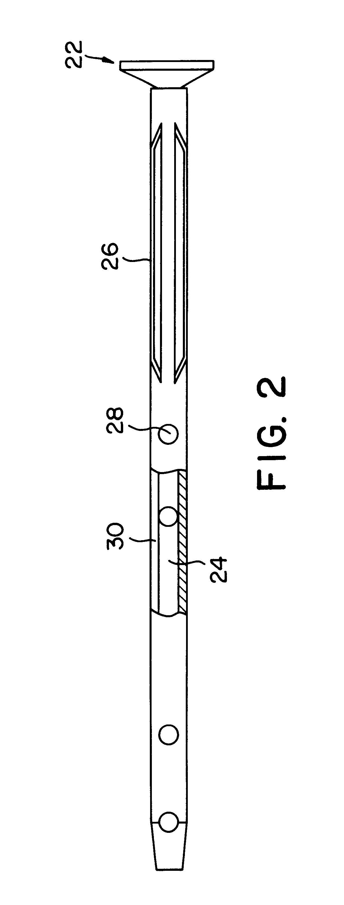
FIGS. 1 and 2 are partial section side views of the intramedullary nail of the present invention. As in conventional intramedullary nails, this intramedullary nail 20 has a rod-form body with a hollow portion 24 inside; and the characterizing feature of this intramedullary nail 20 is that a plurality of fins 26 are formed on the outer circumference of the nail. The intramedullary nail 20 is made of a metal, e.g., a titanium alloy, etc., which does not have a deleterious effect on ma...


PUM


Abstract

An intramedullary nail in which a plurality of fins (26) which protrude radially are formed on the outer circumference of the nail, providing firm internal fixation which makes the nail easy to operate.

Description

The present invention relates to an intramedullary nail which can be suitably used for the purpose of fixating of joints and fracture locations, and more specifically for the purpose of arthrodesis of the ankle joint.BACKGROUND TECHNOLOGYIntramedullary nails are considered to be effective for internal fixation in the treatment of fractures, etc.; and recently, the use of such nails has become common. Specifically, in this method, the intramedullary nail is inserted into the bone marrow through the fracture site, and internal fixation is accomplished by passing at least two transfixation screws through screw holes formed in the intramedullary nail on both sides of the fracture site. In this method, however, depending on the location of the fracture, there may be cases in which the transfixation screws do not pass through.Meanwhile, the destruction of the ankle joint is also common in patient with rheumatoid arthritis, etc. In such cases, arthrodesis of the ankle joint is considered t...

Claims


Application Information

Patent Timeline
Patent Type & Authority Patents(United States)
IPC IPC(8): A61B17/72A61B17/68A61B17/58
CPCA61B17/68A61B17/72A61B17/7283A61B17/7291
Inventor FUJIMORI, JUHROYOSHINO, SHINICHIKOIWA, MASAHITO
Owner FUJIMORI JUHRO
Why Eureka
Try Eureka