Portable scanning spectrophotometer

a scanning spectrophotometer and portability technology, applied in the direction of optical radiation measurement, instruments, spectrometry/spectrophotometry/monochromators, etc., can solve the problems of insufficient precision control of sample registration and movement, significant errors and inconsistencies in color measurement, etc., to improve the registration of samples and improve the maintenance. the effect of consistency

Inactive Publication Date: 2001-03-06
X-RITE
View PDF9 Cites 74 Cited by
  • Summary
  • Abstract
  • Description
  • Claims
  • Application Information

AI Technical Summary

Benefits of technology

The invention is a device that measures the color of a sample. In one embodiment, the device has rollers that move the sample to the color measurement engine. To ensure consistent and accurate color measurement, the device also has tension rollers that resist the movement of the sample. This tension helps keep the sample in a uniform plane and ensures it is aligned properly with the color measurement engine. Additionally, the device has a low-friction media guide that consistently engages the top surface of the sample, improving the registration of the sample with the color measurement engine and ensuring the device rides the top surface of the sample. Overall, the device improves the accuracy and efficiency of color measurement.

Problems solved by technology

The technical problem addressed in this patent text needs to be identified by a senior R&D personnel.

Method used


Image

  • Portable scanning spectrophotometer
  • Portable scanning spectrophotometer
  • Portable scanning spectrophotometer

Examples


Embodiment Construction

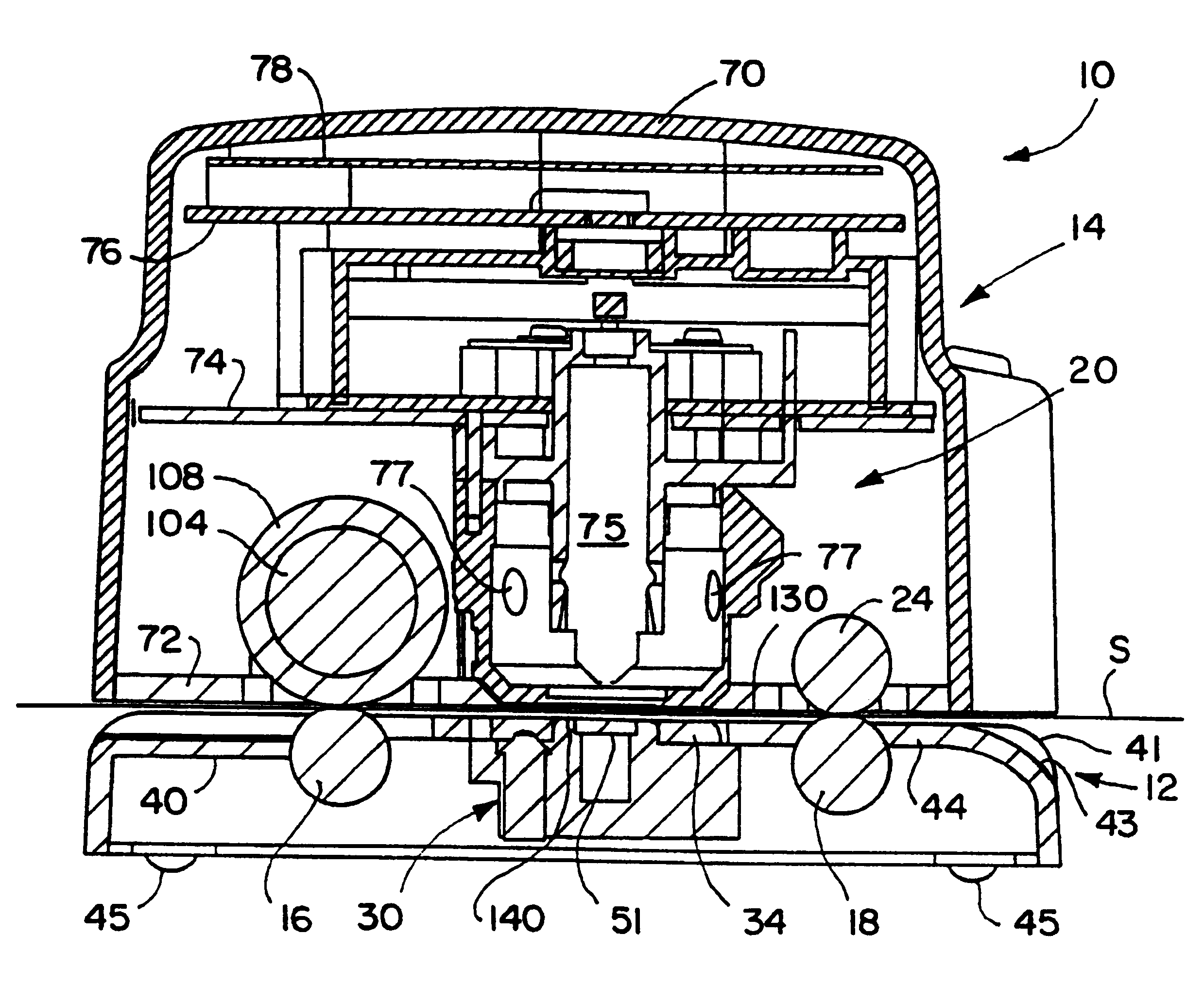
A spectrophotometer constructed in accordance with a preferred embodiment of the present invention is illustrated in the drawings and generally designated 10. As perhaps best illustrated in FIGS. 3 and 10, the spectrophotometer includes a base 12 and an upper assembly 14 supported on the base. The base includes two sets 16 and 18 of idler rollers. The upper assembly 14 includes a spectral analysis engine 20, a drive assembly 22, and tension rollers 24. The engine 20 includes an optical pick-up 75. The drive rollers 22 of the upper assembly engage the idler rollers 16 of the base, and the tension rollers 24 of the upper assembly engage the idler rollers 18 of the base all to partially support the upper assembly 14 on the base 12. The drive rollers 22 pull or draw the sample S (see FIG. 1) through the spectrophotometer 10 and past the optical pick-up 75. The tension rollers 24 create a tension on the sample S to maintain the sample in a consistent plane.

I. Base

The base is perhaps best...


PUM


Abstract

The specification discloses a portable spectrophotometer (10) providing improved movement and control of the sample (S) during analysis. The unit (10) includes a base (12) and an upper assembly (14) supported on the base (12) for floating movement. Both a spectral measurement engine (20) and drive rollers (104) are contained within the upper assembly. The base (12) includes independently suspended idler rollers (16), and the drive rollers (104) engage the idler wheels (16), so that at least a portion of the weight of the upper assembly (14) is borne by the engaging drive rollers (104) and idler rollers (16). The upper assembly (14) therefore floats up and down with samples (S) of varying thickness moving between the rollers (104 and 16). Additional upstream idler rollers (18 and 24) on the base and the upper assembly engage one another and bear a portion of the weight of the upper assembly (14) to create tension in opposition to the drive rollers (104) to hold the sample (S) taut. A planar media guide (130) is located on the underside of the upper assembly (14) and surrounds the spectral engine (20) to engage the sample (S) and reduce flexing and bowing of the sample (S). A manually actuated backer (30) is supported by the base (12) to selectively present to the spectral engine (20) one of two areas (52a and 52b) with different reflective properties. The unit (10) may include a first light source (21) in the spectral engine and a second light source (60) in the backer (30) so that the spectrophotometer (10) is capable of both reflective and transmissive analysis.

Description


Claims


Application Information

Patent Timeline
Owner X-RITE
Why Eureka
Try Eureka