Decorative door guard system

Inactive Publication Date: 2001-03-20
WILKES JOHN M
View PDF2 Cites 11 Cited by
  • Summary
  • Abstract
  • Description
  • Claims
  • Application Information

AI Technical Summary

Benefits of technology

to indicate a device of the type disclosed above which avoids the disadvantages inherent in the state of the art. In particular, the device is to protect door from dirt, grease and grime around door knobs, and also protects door from scratches and/or dents. It should be capable of use on any interior door, capable of fitting over existing door knob without disassembly of door required. Removability should allow the invention to be mov

Problems solved by technology

One area that also sees frequent contact with a user's hand but is not afforded any protection is that area of a door around a door handles.
In this manne

Method used


Image

  • Decorative door guard system
  • Decorative door guard system
  • Decorative door guard system

Examples


Embodiment Construction

of the Figures

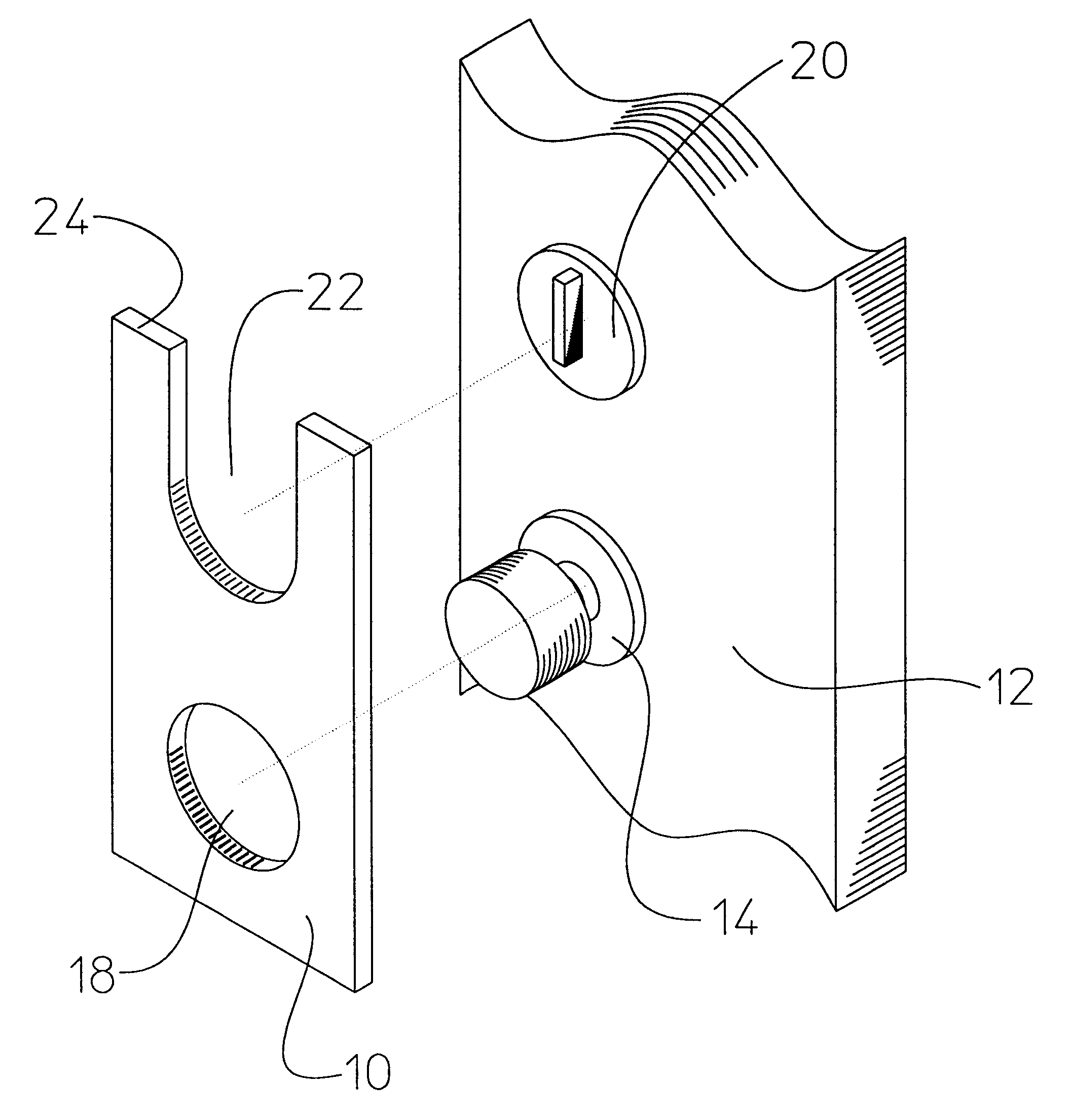
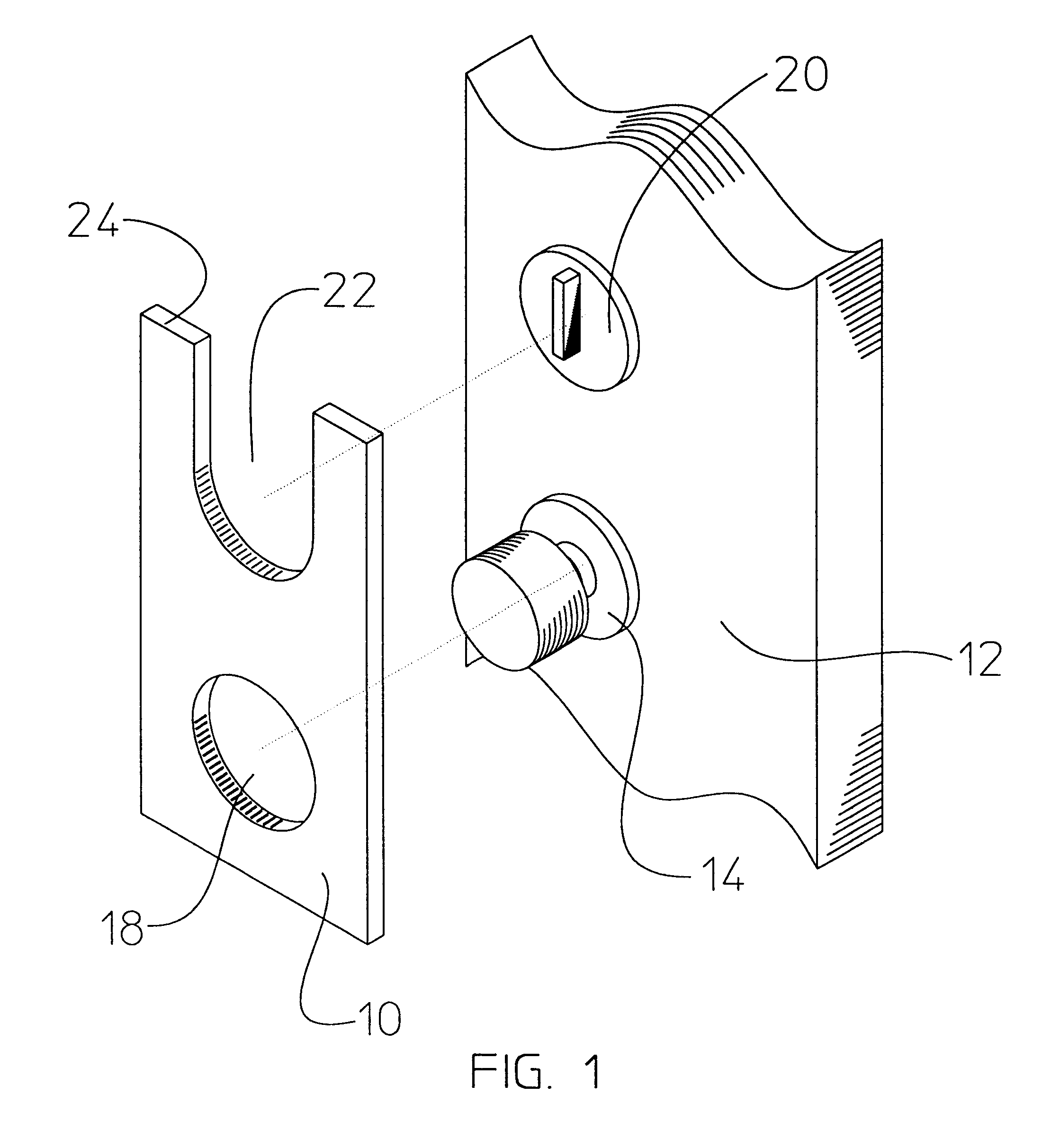
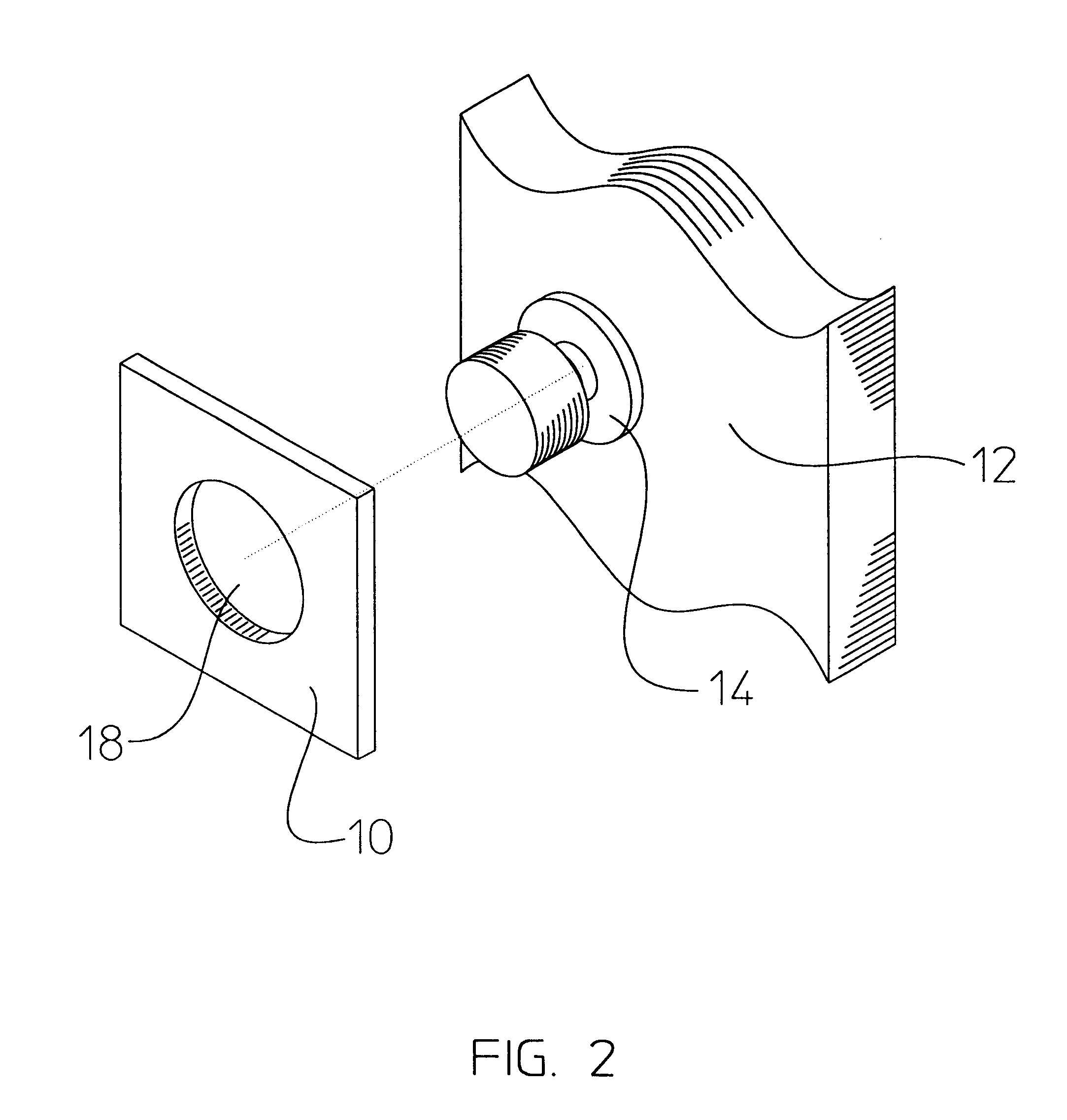
Referring now to FIGS. 1-3, a door guard apparatus 10 is shown, according to the present invention, for application to a door 12 for shielding and protection of the surface area about a door knob 14. The door guard 10 forms a knob access orifice 18 near the middle and within the outer perimeter of the decorative outer plate 30. Considered as an embodiment congruent with the present teachings, for doors 12 having a deadbolt lock 20 it is envisioned that the door guard 10 will additionally form a deadbolt access indentation 22 formed along the upper edge 24 of the decorative outer plate 30.

As best shown in conjunction with FIG. 3, shown is the preferred embodiment of the present invention in which the door guard 10 is formed of a plurality of layers of material, specifically, a first layer 32, forming an attachment means for affixing to the surface of the door 12, and anticipated as being an adhesive layer for firm but removable attachment to the door 12. The adhesive is...


PUM


Abstract

A door guard apparatus is provided having a first layer of adhesive, a middle layer providing structural rigidity and resistance to structural penetration, and a decorative outer overlay affixed to the middle layer. A knob access penetrates all the layer to allow for mounting about a doorknob.

Description

1. Field of the InventionThe present invention relates generally to escutcheons and door guards and, more particularly, to a decorative door guard system.2. Description of the Related ArtThere currently exists a wide variety of products, generally available, to protect paint and home finishes such as plastic corner protectors for outside wall corners, clear plastic switch plates that protect the finish around electrical wall switches, and other similar devices. One area that also sees frequent contact with a user's hand but is not afforded any protection is that area of a door around a door handles.In the related art, the following design patents disclose a door guard or escutcheon for a door lock: U.S. Pat. No. D 411,732 issued in the name Chamberlain; U.S. Pat. No. D 326,996 issued in the name Birch; U.S. Pat. No. D 326,806 issued in the name of Marques; U.S. Pat. No. D 247,845 issued in the name of Palm, Jr.; U.S. Pat. No. D 246,503 issued in the name of Clayton; and U.S. Pat. No...

Claims


Application Information

Patent Timeline
IPC IPC(8): E05B15/02E05B15/00
CPCE05B15/02
Inventor WILKES, JOHN M.
Owner WILKES JOHN M
Why Eureka
Try Eureka