Steering control for watercraft

a technology for controlling the steering mechanism and watercraft, which is applied in the direction of steering initiation, special purpose vessels, vessel construction, etc., can solve the problems of reducing the overall performance, and reducing the size of the structure needed to house the mechanism

Inactive Publication Date: 2001-03-20
YAMAHA MOTOR CO LTD
View PDF6 Cites 33 Cited by
  • Summary
  • Abstract
  • Description
  • Claims
  • Application Information

AI Technical Summary

Problems solved by technology

There have, however, been several design problems with the prior art.
First, an adjustable steering mechanism typically occupies more space that a fixed steering mechanism resulting in a larger structure needed to house the mechanism.
The enlargement of the housing typically increases the overall wind resistance of the watercraft and subsequently degrades the overall performance.
A further problem with an adjustable steering mechanism stems from the fact that the steering mechanism is typically attached to a steering controller device in the engine compartment of the watercraft.
A problem arises when the steering mechanism is moving or rotating with respect to the engine compartment thereby creating a large area in which water can enter.
Yet another problem typically associated with an adjustable steering mechanism is the visibility of the display.
Display visibility problems exist when the display is fixed on the watercraft and is blocked by any part of the steering mechanism.
Likewise, the visibility of displays that move with the steering mechanism can also have problems if the movement of the mechanism locates the display in a position that cannot be seen by the operator.
A further problem associated with an adjustable steering column is operator comfort.
This problem occurs when the movement of the steering mechanism locates the associated controls in ergonomically uncomfortable positions.

Method used


Image

  • Steering control for watercraft
  • Steering control for watercraft
  • Steering control for watercraft

Examples


Embodiment Construction

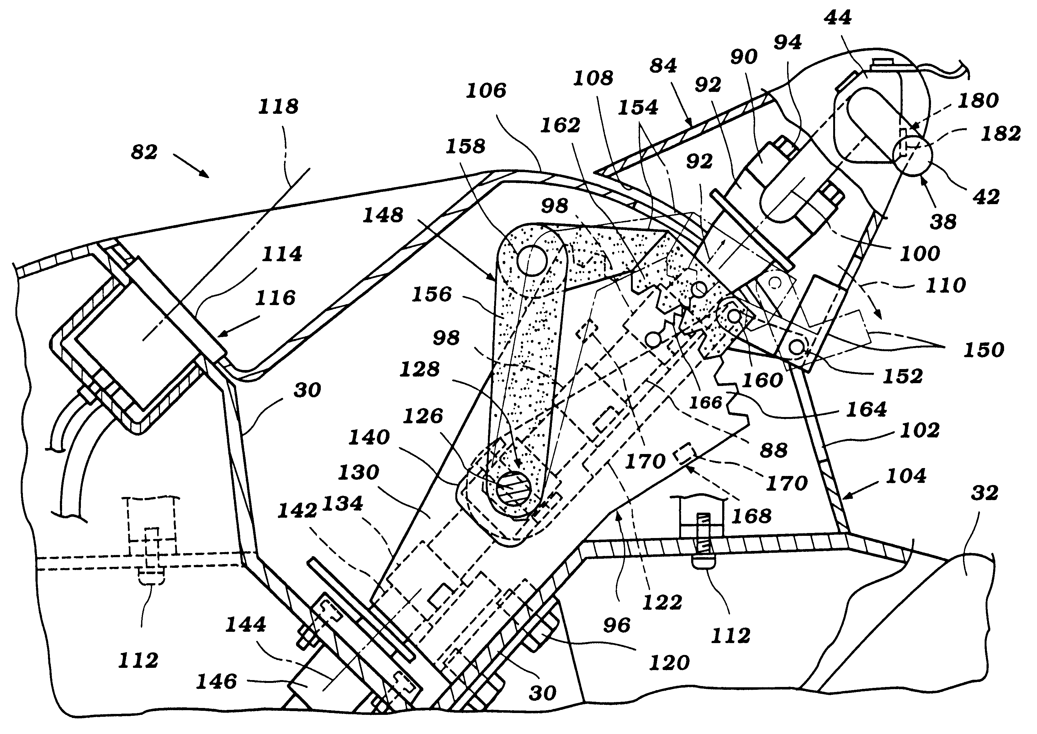
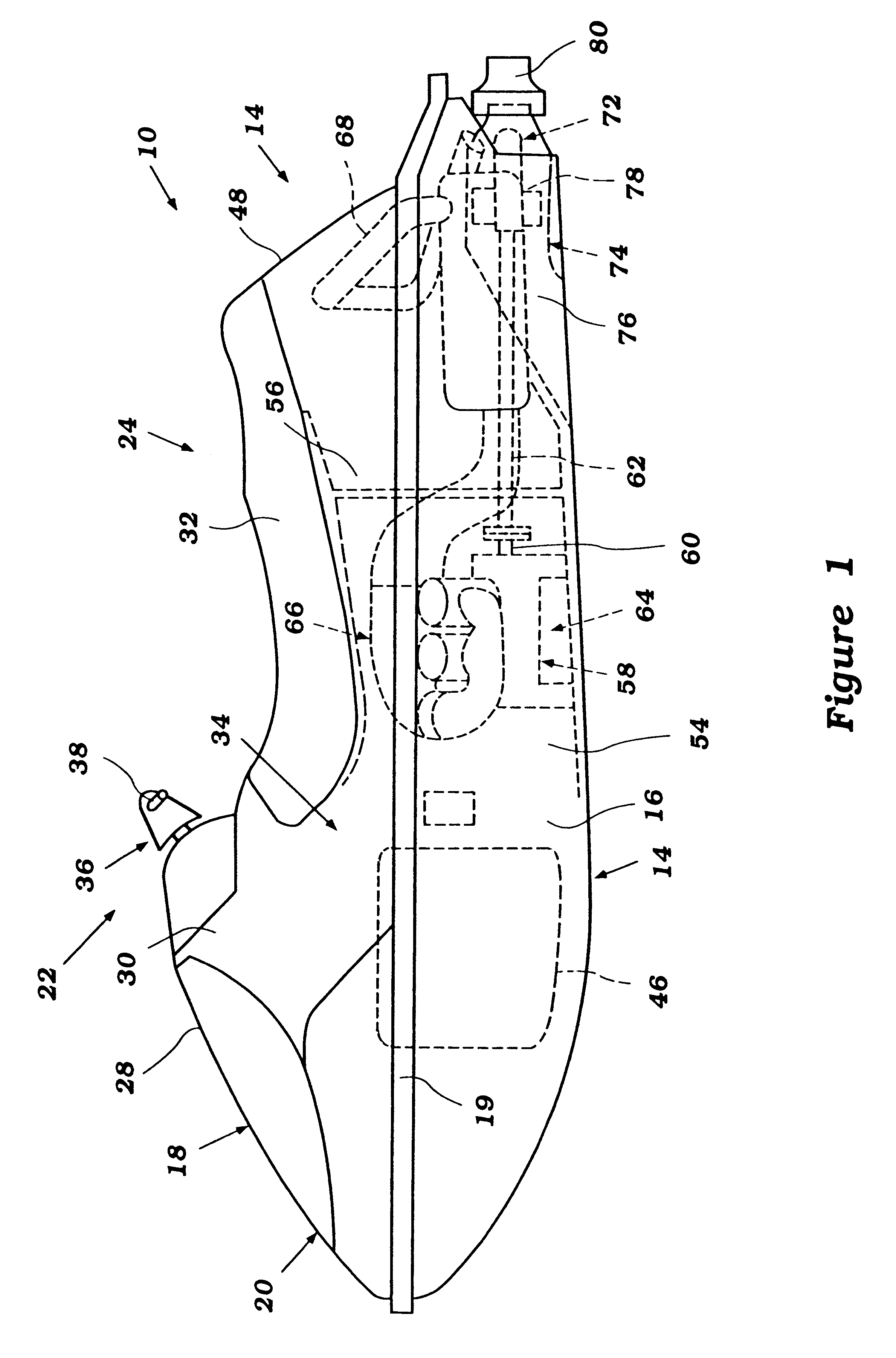
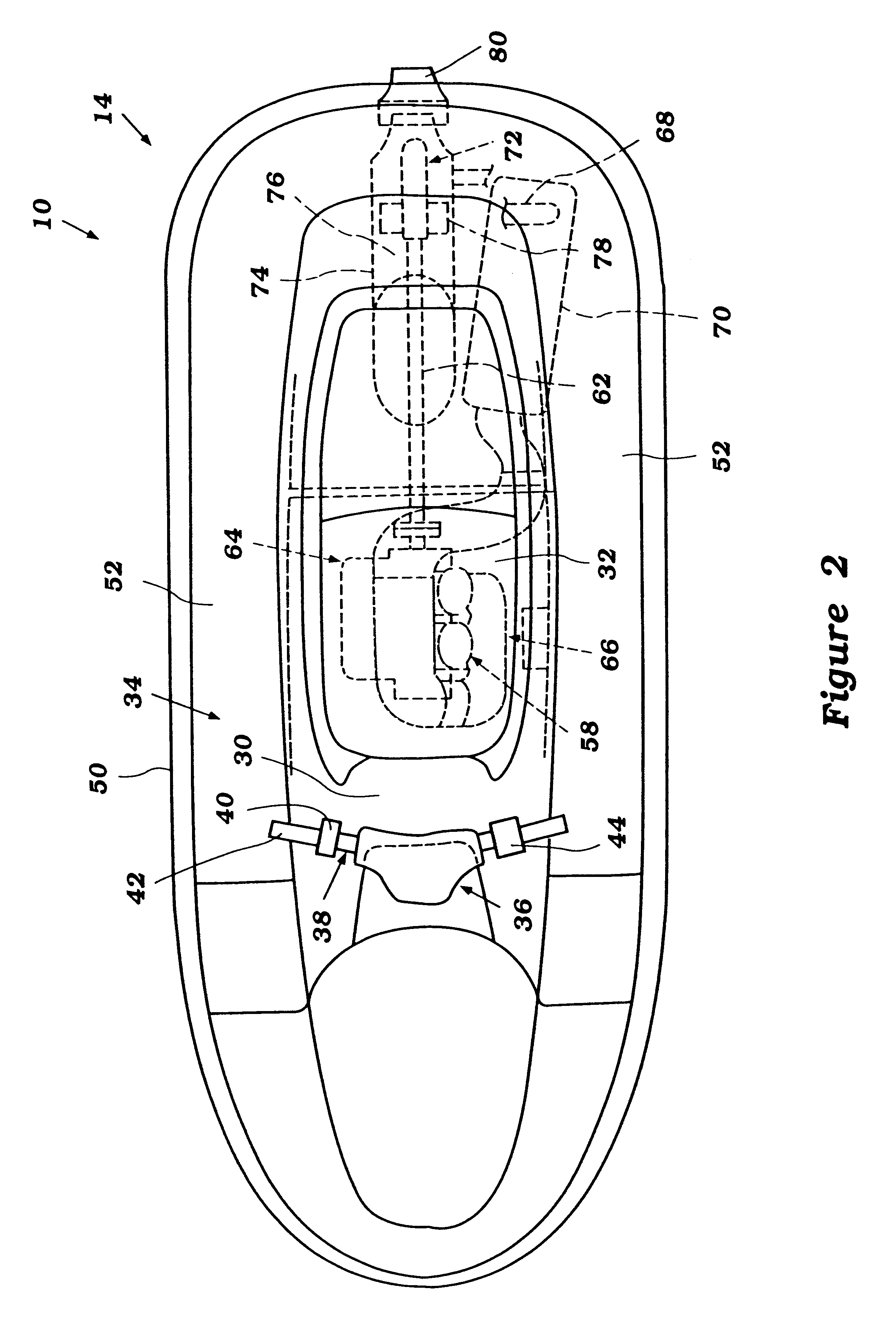
FIGS. 1 and 2 illustrate a watercraft incorporating an adjustable steering mechanism configured in accordance with a preferred embodiment of the present invention. The adjustable steering mechanism has particular utility with a personal watercraft, and therefore is illustrated in connection with such a vehicle. It is contemplated, however, that the adjustable steering mechanism can be used with other types of vehicles as well, such as, for example, but without limitation, small jet boats and the like.

With initial reference to FIGS. 1 and 2, the watercraft 10 includes a hull 14 formed by a lower hull section 16 and an upper deck section 18. The hull sections 16, 18 are formed from a suitable material such as, for example, a molded fiberglass reinforced resin. The lower hull section 16 and the upper deck section 18 are fixed to each other around the peripheral edges 19 in any suitable manner.

As viewed in the direction from the bow to the stem of the watercraft, the upper deck section ...


PUM


Abstract

The invention provide an adjustable steering mechanism for a watercraft. The watercraft has a hull including a main body, an upper wall engaging the hull and cooperating therewith to define an engine compartment for housing an engine. The engine has an output shaft arranged to drive a water propulsion device of the watercraft The upper wall has a top surface and a bottom surface. The bottom surface facing forwardly towards engine compartment. A first steering means extends through the upper wall and is in communication with a steering mechanism of the watercraft. The first steering means also coupled to a steering shaft and handle. The steering shaft and handle are journalled for rotation about a first axis with respect to a rotation member. The rotation member being rotatably affixed to the top side of the upper wall opposite the engine compartment thereby allowing the rotation of the rotation member and the steering shaft and handle in a forward and rearward direction about a second axis generally perpendicular to a longitudinal axis of the watercraft and the first axis and whereby the steering shaft and handle is independently rotatable with respect to the rotation member about the first axis.

Description

1. Field of the InventionThe present invention relates in general to a personal watercraft, and in particular to an adjustable steering mechanism for the personal watercraft.2. Description of Related ArtPersonal watercraft have become popular in recent years. This type of watercraft is sporting in nature; it turns swiftly, is easily maneuverable, and accelerates quickly. Personal watercraft today commonly carry one rider and one or two passengers.A relatively light weight, small hull of the personal watercraft defines an engine compartment below a rider's area. An internal combustion engine frequently lies within the engine compartment in front of a tunnel formed on the underside of the watercraft hull. The internal combustion engine commonly powers a jet propulsion device located within the tunnel. An impeller shaft commonly extends between the engine and the propulsion device for this purpose. Such small watercraft today are capable of traveling at high rates of speed.Personal wat...

Claims


Application Information

Patent Timeline
Patent Type & Authority Patents(United States)
IPC IPC(8): B63H21/22B63H21/00B63B35/73B63H25/10B63H25/06B63H25/02
CPCB63B35/731B63H21/213B63H25/10B63H2025/024B63B34/10
Inventor MADACHI, TAKAAKIYOSHIDA, TATSUYAHARADA, MASAHIRO
Owner YAMAHA MOTOR CO LTD
Why Eureka
Try Eureka