Stapling apparatus and method for heart valve replacement

a heart valve and apparatus technology, applied in the field of minimally invasive surgical procedures and equipment, can solve the problems of requiring replacement, affecting the function of the valve, and requiring replacement, and is typically time-consuming and difficult, and is particularly time-consuming

Inactive Publication Date: 2001-03-20
UNITED STATES SURGICAL CORP
View PDF5 Cites 493 Cited by
  • Summary
  • Abstract
  • Description
  • Claims
  • Application Information

AI Technical Summary

Benefits of technology

A method of installing a heart valve within a patient is also provided which includes the steps of accessing a site within a heart from which a natural heart valve has been removed; lowering a prosthetic heart valve into position within the site in the heart; positioning a surgical stapler having at least one staple assembly removably held on a distal end thereof adjacent the prosthetic heart valve within the site in the heart; driving a first leg of the at least one staple assembly through a peripheral cuff of the prosthetic heart valve; and crimping a second leg of the at least one staple assembly in a direction toward the first leg such that the second leg pierces a portion of heart tissue surrounding the prosthetic heart valve, thereby securing the prosthetic heart valve to the surrounding heart tissue. The prosthetic heart valve is preferably removably mounted on a distal end of the surgical stapler such that the lowering step and the positioning step are performed simultaneously.

Problems solved by technology

Various factors, such as, for example, calcification, may result in the mitrial or aortic valves becoming impaired or functionally inoperative requiring replacement.
Since the conventional heart valve replacement techniques are exclusively manual procedures, they are typically time consuming and difficult.
While the above described procedures are sufficient to successfully secure a heart valve within the heart, they are particularly time consuming.

Method used


Image

  • Stapling apparatus and method for heart valve replacement
  • Stapling apparatus and method for heart valve replacement
  • Stapling apparatus and method for heart valve replacement

Examples


Embodiment Construction

Various embodiments are disclosed herein which relate to installation tools and methods for quickly and efficiently positioning and securing a synthetic replacement heart valve within a heart without the necessity of manually suturing the valve in place. The disclosed tools and methods accomplish this objective by providing a stapling apparatus, and method of use thereof, for securing a prosthetic heart valve to a human heart via a plurality of staples secured in a predetermined position within a site in the heart.

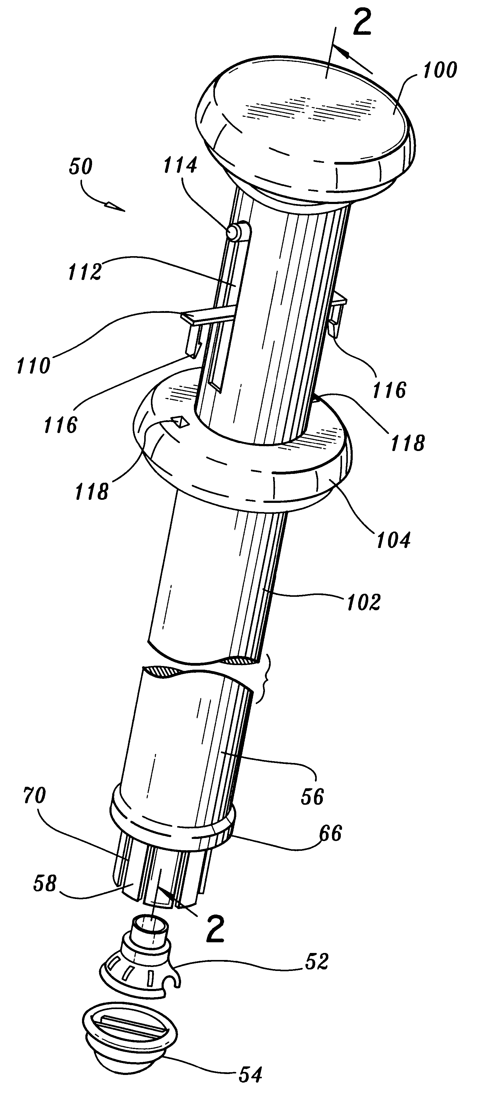
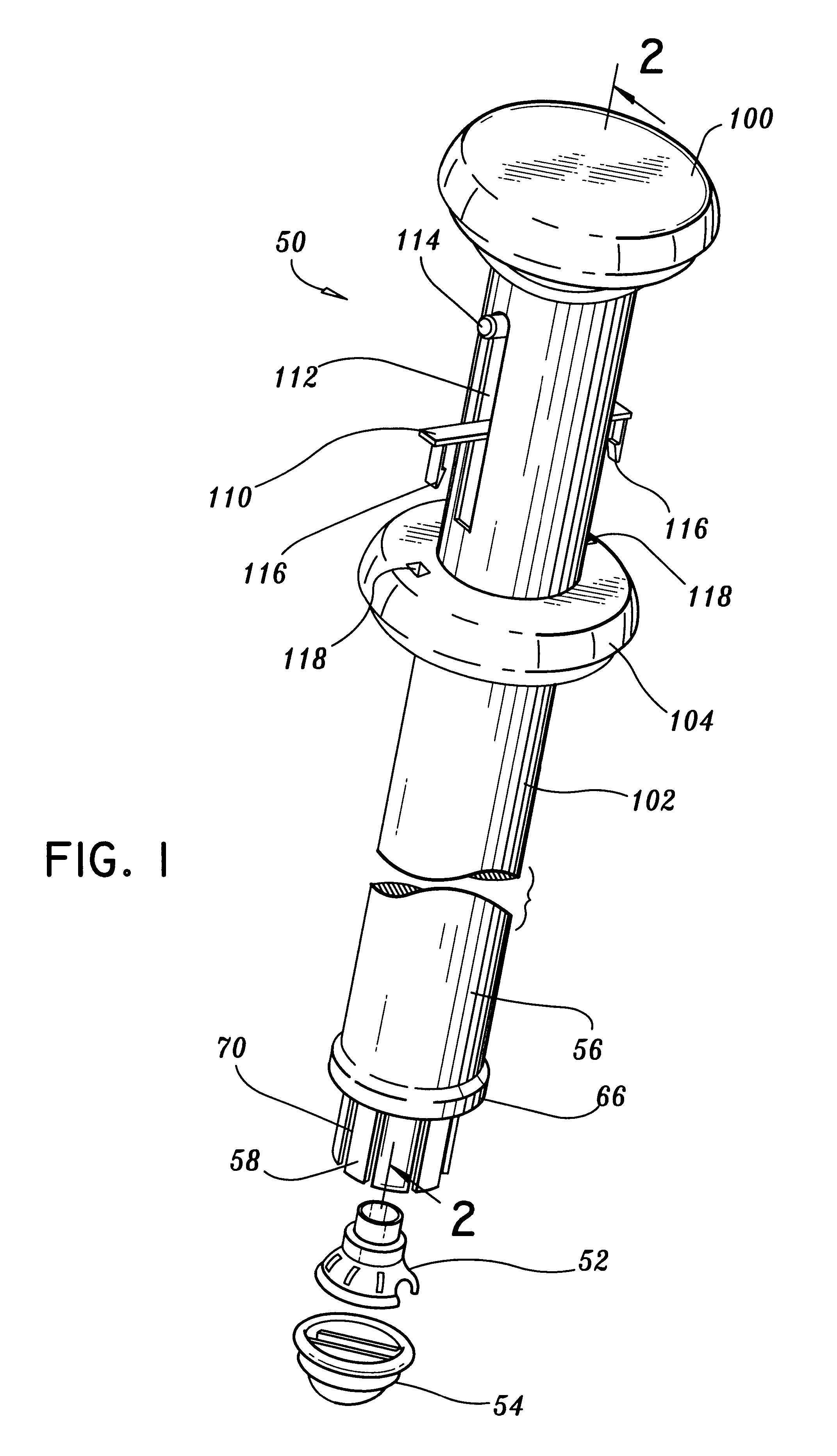
Referring now to the drawings in detail, and initially to FIG. 1, stapling apparatus 50 in accordance with the present disclosure is illustrated in a perspective view. Stapling apparatus 50 is illustrated in FIG. 1 along with a heart valve holder 52 and a prosthetic heart valve 54. Stapling apparatus 50, heart valve holder 52 and prosthetic heart 54 are detachable from each other.

Stapling apparatus 50 generally includes a knob 100 on a proximal end thereof, a cylindrical b...


PUM

PropertyMeasurementUnit
angleaaaaaaaaaa
circumferenceaaaaaaaaaa
sizeaaaaaaaaaa

Abstract

A surgical stapler for securing a prosthetic heart valve within a patient generally includes a first cylindrical portion for carrying at least one staple assembly on a distal end thereof; a second cylindrical portion positioned concentrically about the first cylindrical portion and having a camming arm on a distal end thereof, the camming arm configured to cam the at least one staple assembly radially outward and drive the at least one staple assembly distally such that a first leg of the at least one staple assembly penetrates a cuff of the prosthetic heart valve and a second leg of the at least one staple assembly pierces a portion of heart tissue surrounding the prosthetic heart valve, as the second cylindrical portion is moved distally relative to the first cylindrical portion; and a third cylindrical portion positioned concentrically about the second cylindrical portion and having an anvil flange on a distal end thereof, the anvil flange configured to crimp the second leg of the at least one staple assembly toward the first leg of the at least one staple assembly to secure the prosthetic heart valve to the surrounding heart tissue as the third cylindrical portion is moved relative to the second cylindrical portion. A method of installing a heart valve within a patient which includes the steps of accessing a site within a heart from which a natural heart valve has been removed; lowering a prosthetic heart valve into position within the site in the heart; positioning a surgical stapler having at least one staple assembly removably held on a distal end thereof adjacent the prosthetic heart valve within the site in the heart; driving a first leg of the at least one staple assembly through a peripheral cuff of the prosthetic heart valve; and crimping a second leg of the at least one staple assembly in a direction toward the first leg such that the second leg pierces a portion of heart tissue surrounding the prosthetic heart valve, thereby securing the prosthetic heart valve to the surrounding heart tissue.

Description

1. Technical FieldThe subject disclosure relates to minimally invasive surgical procedures and apparatus and, more particularly, to instruments and methods for performing heart valve replacement surgery.2. Background of Related ArtThe diagnosis and treatment of coronary disease and related conditions often requires repair or replacement of the valves located within the heart. Various factors, such as, for example, calcification, may result in the mitrial or aortic valves becoming impaired or functionally inoperative requiring replacement. Where replacement of a heart valve is required, in general, the dysfunctional valve is cut out and replaced with either an artificial, synthetic heart valve or a harvested porcine heart valve. The replacement valve is typically sutured in place of the original valve.Access to the heart in a patient's thoracic cavity is achieved by making a longitudinal incision in the chest. This procedure, referred to as a median sternotomy includes cutting throug...

Claims


Application Information

Patent Timeline
Patent Type & Authority Patents(United States)
IPC IPC(8): A61B17/068A61B17/072A61F2/24A61B17/00
CPCA61B17/072A61F2/2427A61B17/068A61B17/1155A61B2017/00243A61B2017/07214A61F2/2403
Inventor ROBERTSON, JOHN CHARLESRATCLIFF, KEITHMOULDER, BRIAN W.
Owner UNITED STATES SURGICAL CORP
Why Eureka
Try Eureka