Pneumatic tire having directional tread pattern

a pneumatic tire and groove technology, applied in the direction of non-skid devices, vehicle components, transportation and packaging, etc., can solve the problems of easy uneven wear at the block, pattern noise worsening, pattern noise increasing,

Inactive Publication Date: 2001-03-27
BRIDGESTONE CORP
View PDF15 Cites 17 Cited by
  • Summary
  • Abstract
  • Description
  • Claims
  • Application Information

AI Technical Summary

Problems solved by technology

However, in such conventional pneumatic tires, it is easy for uneven wear to occur at the blocks which are defined by the inclined main grooves in vicinities of the end portions of the tread.
When the tire is new, both wet properties and low pattern noise are achieved, but as uneven wear occurs, the pattern noise worsens.
It is known that when uneven wear occurs, pattern noise increases.
Heel-and-toe wear is wear which occurs at the time the block moves apart from the road surface, i.e., due to the sliding at the time of kick-out from the road surface.
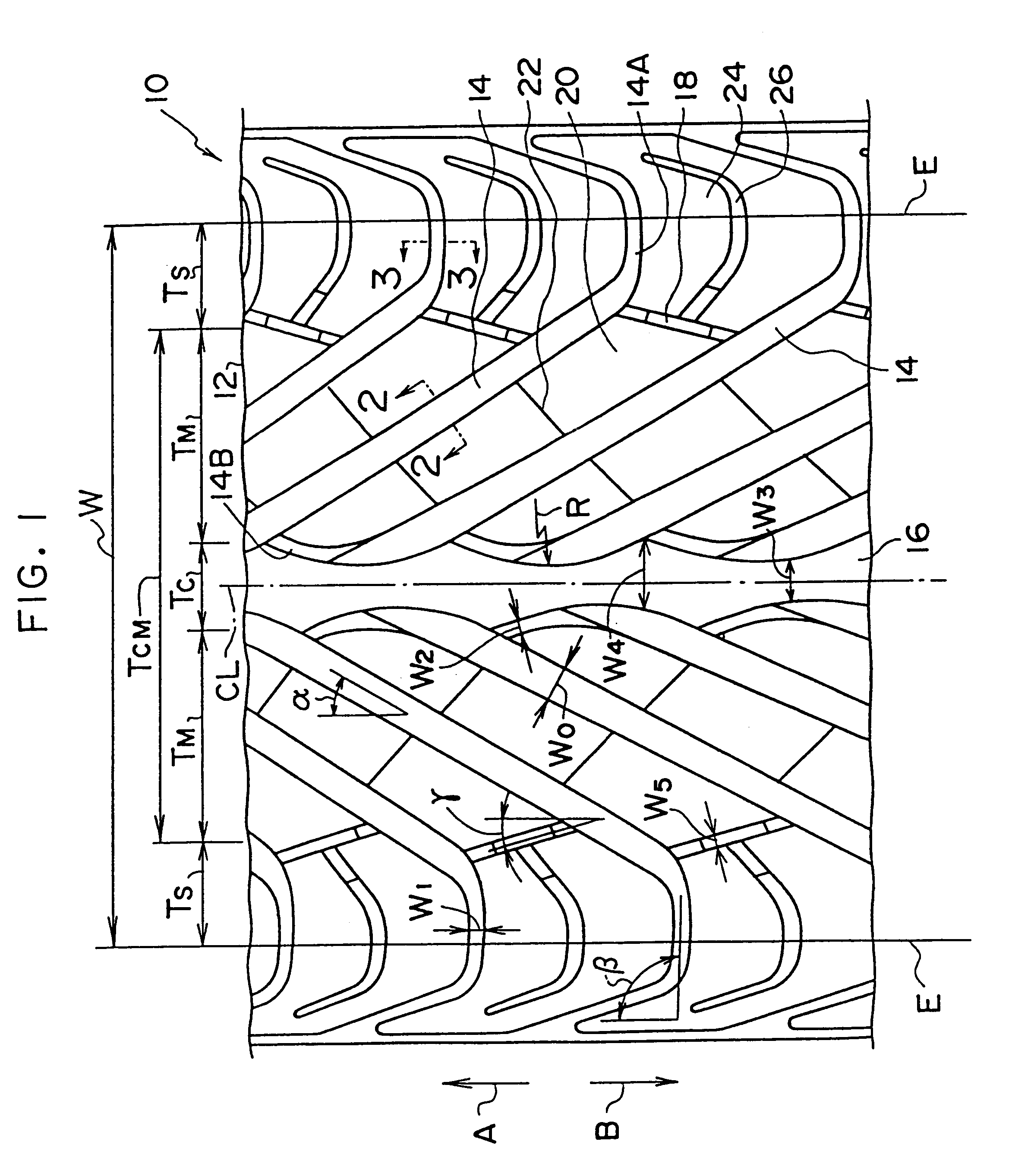
Here, when the angle of inclination .theta.1 of the block step-in end side at the portion of the inclined main groove from the tread center to the auxiliary groove is less than 0.degree. (i.e., when the groove wall surface is inclined toward the opposite side such that an inverse taper is formed), a convex portion of a mold for forming the inclined main groove gets caught at the time of removing the tire from the mold, and it is difficult to remove the tire from the mold.
On the other hand, when the angle of inclination .theta.1 of the block step-in end side at the portion of the inclined main groove from the tread center to the auxiliary groove is greater than 5.degree., the rigidity of the block increases, and therefore, the reduction in the striking sound is insufficient.
Thus, there is a relatively large amount of wear at the kick-out side, and it is easy for uneven wear to occur.
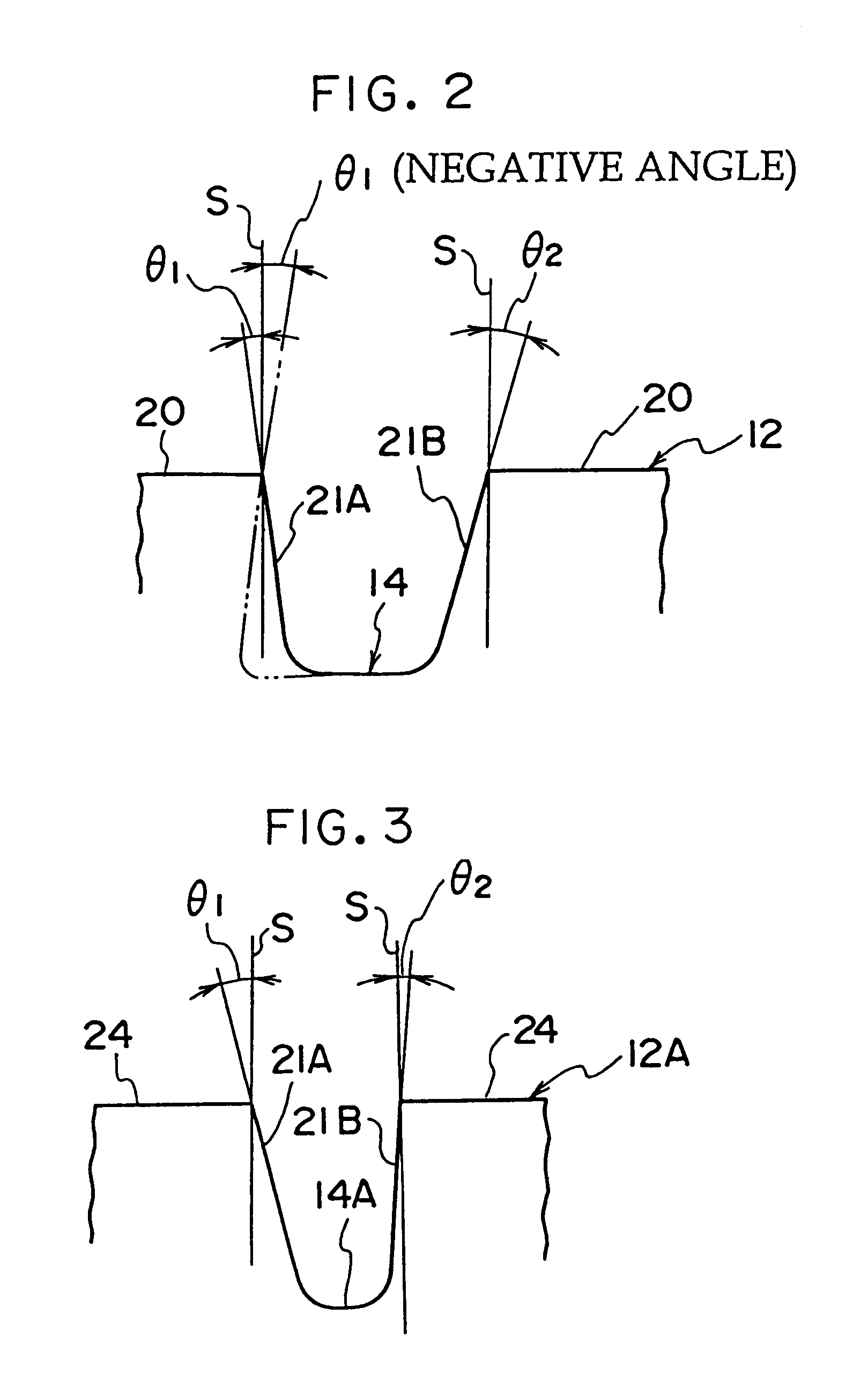
When the angle of inclination .theta.2 of the block kick-out end side at the portion of the inclined main groove from the auxiliary groove to the tread end is less than 0.degree. (i.e., when the groove wall surface is inclined toward the opposite side such that an inverse taper is formed), a convex portion of a mold for forming the inclined main groove gets caught at the time of removing the tire from the mold, and it is difficult to remove the tire from the mold.
On the other hand, when the angle of inclination .theta.2 of the block kick-out end side at the portion of the inclined main groove from the auxiliary groove to the tread end is greater than 5.degree., the rigidity becomes large, and it is easy for uneven wear to occur.
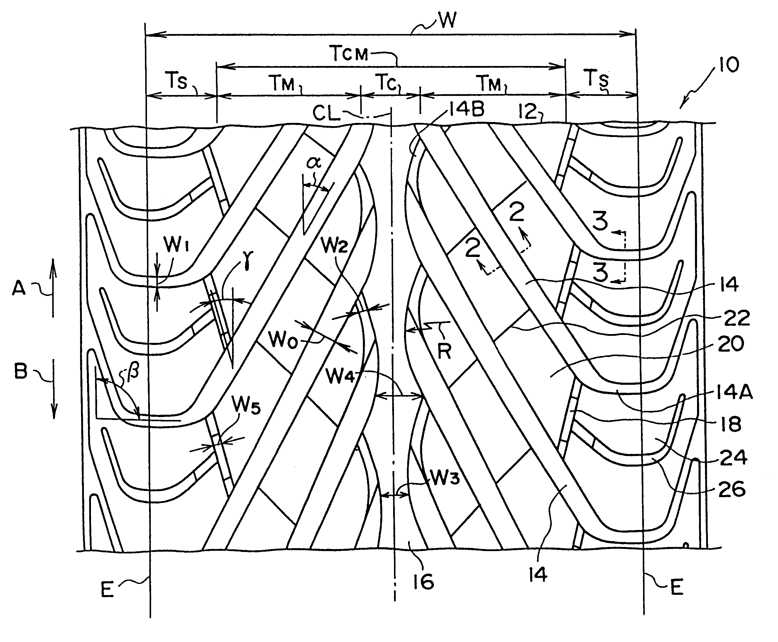
Here, when the angle of inclination .alpha., with respect to the tire circumferential direction, of the inclined main groove 14 at the tread intermediate region TM is less than 15.degree., the rigidity required by the blocks 20 between the inclined main grooves 14 is not imparted, which leads to a deterioration in operational stability and the occurrence of uneven wear.
In contrast, when the angle of inclination .alpha. exceeds 45.degree., the water-removing ability cannot be ensured.
On the other hand, if the radius of curvature is too small, the rigidity of the rib 16 in a vicinity of the final end of the inclined main groove 14 becomes excessively low, and it is easy for uneven wear to occur.
Further, in a case in which the grooves are formed straight, the corner portions of the blocks have more acute angles, which promotes uneven wear.
The reason is that when the opening position is in a range exceeding 85%, the rigidity of the side portion block 24 decreases, which leads to insufficient traction and insufficient driving properties, and the operational stability deteriorates.
On the other hand, if the opening position is in a range less than 50%, the desired ground-contact pressure distribution cannot be obtained.
The reason is that if the interval is less than 10%, the negative ratio of the tread center region TC becomes excessively large, and therefore, the operational stability and the linearity at the time of steering (the relationship between the steering angle and the steering force varying linearly) deteriorates.
On the other hand, if the interval is greater than 30%, an improvement in the water-removing ability cannot be expected.

Method used


Image

  • Pneumatic tire having directional tread pattern
  • Pneumatic tire having directional tread pattern
  • Pneumatic tire having directional tread pattern

Examples


Embodiment Construction

Experimental Example Tires were filled to an internal pressure of 2.5 kg / cm.sup.2, were installed on an actual vehicle (a European middle class sedan) carrying a load of two occupants, and the water-removing ability, pattern noise, pattern noise of the worn tire, and operational stability were tested.

The tires (tire size 225 / 45ZR17) used for the Comparative Examples 1, 2 and the Example all had the same tread pattern (the tread pattern of FIG. 1), but the angles of inclination of the groove wall surfaces of the inclined main grooves were varied as shown in Table 1.

The testing methods were as follows.

1. Water-Removing Ability: The vehicle traveled on a propulsion 10 mm wet road surface, and the speed at which hydroplaning occurred was measured.

2. Pattern Noise: A microphone was placed at the position of the ear of the driver, and the noise at the time the vehicle traveled at 60 km / h on a straight, flat road was measured.

3. Pattern Noise of the Worn Tire: After the tire had traveled o...


PUM


Abstract

At a portion of an inclined main groove from a tread center to an auxiliary groove of a pneumatic tire, an angle of inclination theta1 of a groove wall surface at a block step-in end side is set to be smaller than an angle of inclination theta2 of a groove wall surface at a block kick-out end side. Therefore, rigidity of step-in ends of blocks defined by inclined main grooves is lowered such that a striking sound can be reduced. Further, at a portion of the inclined main groove from the auxiliary groove to a tread end, an angle of inclination theta1 of a groove wall surface at a block step-in end side is set to be greater than an angle of inclination theta2 of a groove wall surface at a block kick-out end side. Therefore, rigidity of kick-out end sides of blocks defined by the inclined main grooves is lowered. Heel-and-toe wear which occurs at the kick-out end sides is suppressed, and an increase in pattern noise caused by heel-and-toe wear is suppressed.

Description

1. Field of the InventionThe present invention relates to a pneumatic tire having inclined grooves at the tread, and in particular, to a pneumatic tire in which both wet properties are improved and pattern noise is reduced.2. Description of the Related ArtIn the field of pneumatic tires, there is an increasing number of examples of pneumatic tires utilizing an inclined main groove pattern in order to achieve both wet properties and a reduction in pattern noise.However, in such conventional pneumatic tires, it is easy for uneven wear to occur at the blocks which are defined by the inclined main grooves in vicinities of the end portions of the tread. When the tire is new, both wet properties and low pattern noise are achieved, but as uneven wear occurs, the pattern noise worsens.Further, after the tire becomes worn, the superior reduction in pattern noise which the tire exhibits over a conventional straight pattern tire disappears, and in some cases, the conventional tire may even be ...

Claims


Application Information

Patent Timeline
Patent Type & Authority Patents(United States)
IPC IPC(8): B60C11/04B60C11/03B60C11/13B60C11/11B60C11/117
CPCB60C11/0302B60C11/0309B60C11/13B60C11/1323B60C11/033B60C2011/0388B60C2011/0374
Inventor TAKAHASHI, ICHIRO
Owner BRIDGESTONE CORP
Why Eureka
Try Eureka