Bulkhead for retaining a cargo in a container

Inactive Publication Date: 2001-03-27
PODD STEPHEN D
View PDF27 Cites 38 Cited by
  • Summary
  • Abstract
  • Description
  • Claims
  • Application Information

AI Technical Summary

Benefits of technology

The bulkhead and its parts cooperate such that when it is placed in the container with the first side of the center wall section facing the front wall, it creates a cargo space between the front wall and the first side of the center wall of the bulkhead. Additionally, each of the flaps rest against their respective side wall and the floor at less than 180.degree. with the plane of the first side of the bulkhead's center wall section. These flaps fit against the side walls and floor in a sealed fit, and thus prevent the escape of cargo where the center wall section of the bulkhead meets the floor and side walls.
In yet another variation of the invention, two separate tubes are used. FIG. 26 depicts a bulkhead 179 with a left side flap 175 and a right side flap 176. Therein adjacent on the left edge of the bulkhead 179A, inflatable tube 172 is adjacent the left side flap, and at the right edge of the bulkhead 179B, inflatable tube 171 is adjacent the right side flap. These tubes, when inflated, would force the respective side flap against the adjacent portion of the container wall and provide for a better sealed fit.

Problems solved by technology

The cargo or product being shipped will often leak out through these gaps.
However, this method can prove expensive, given the extra work required.
Additionally, it can prove a dangerous method in that, while climbing in or out, the worker could accidently fall or trip and perhaps injure himself / herself.
Also, these plywood bulkheads are heavy and clumsy, and are expensive to manufacture.
Another problem with the current art bulkhead as depicted in FIGS. 1 and 2 is the fact that, during loading of many dry bulk, flowable cargos, dust generated by the loading process vents through the opening created by the gap 19 between the top of the bulkhead 25 and the ceiling 21 of the container.

Method used


Image

  • Bulkhead for retaining a cargo in a container
  • Bulkhead for retaining a cargo in a container
  • Bulkhead for retaining a cargo in a container

Examples


Embodiment Construction

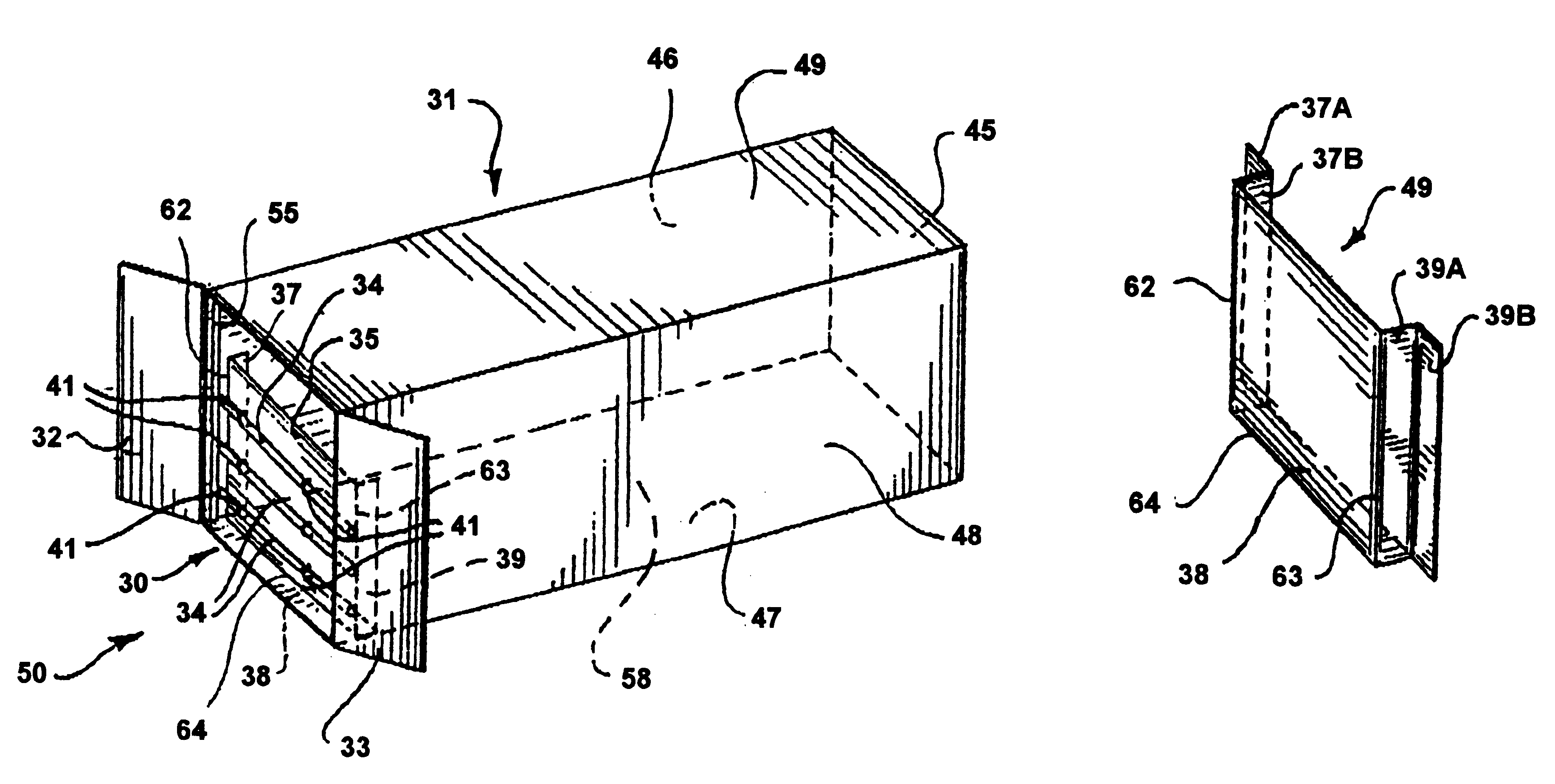
FIG. 3 depicts the preferred embodiment of the present invention. Cargo container 31, a standard ISO cargo container of anywhere from 20 to 40 feet long and generally 8 feet wide and 8 to 9 feet high, has a floor 47, a right side wall 48, a left side wall 46, a top 49, and a front wall 45. Such ISO containers are made out of aluminum, steel, or a combination of these and other materials, and have become standard in the shipping industry. The container also has a rear opening 50 with rear doors 32 and 33.

Bulkhead 30, located at the rear of the container 31, has a center wall section 35, a left side flap 37, a right side flap 39, and a lower flap 38. The bulkhead 30 of the present invention is made of a thin, light, flexible and semi-rigid material. The preferred material for making the bulkhead 30 is cardboard, in particular corrugated cardboard, with a double-walled or triple-walled thickness. Other potential materials are plastic of a sufficiently rigid but flexible construction, a...


PUM


Abstract

A bulkhead for use with cargo containers that carry dry flowable cargo. The bulkhead has flaps on the bottom edge and on both side edges. When the bulkhead is installed in a container, the flap on the bottom folds against the floor of the container to form a seal. The side flaps also fold against the sides of the container to form seals. The seals prevent the dry flowable cargo, when loaded in the container, from leaking out of the container. This eliminates the need for a liner in the container to hold the cargo.

Description

1. Field of the InventionThis invention relates in general to dry bulk cargo containers, and in particular to a method or apparatus for closing off the rear end of such a container. More specifically, it relates to providing a partially sealing closure for the rear of a container.2. Background ArtUse of standard-type ISO cargo containers has come into widespread use in the shipping industry in the last thirty to forty years. Dry bulk, flowable cargos make up one class of cargo shipped in these containers. Use of the container to transport a dry bulk, flowable cargo of up to 44,000 pounds avoids the necessity of having to package small amounts, fifty pounds to one ton, of the cargo in separate packaging, and then place them in the container. The dry bulk cargo is generally blown into or deposited in the container by a gravity feed system.A number of methods exist for enclosing and sealing the cargo in the container for transport. One involves using a large plastic liner in the contai...

Claims


Application Information

Patent Timeline
IPC IPC(8): B60P7/14B60P7/06B65D90/04
CPCB60P7/14B65D90/046
Inventor PODD, STEPHEN D.
Owner PODD STEPHEN D
Why Eureka
Try Eureka