Sensor suite and communication system for cargo monitoring and identification

a communication system and cargo technology, applied in the field of sensors, can solve the problems of limited throughput, limited deployment, hostile rf environment in which this link must be established, etc., and achieve the effect of long integration tim

Inactive Publication Date: 2006-03-28
RAYTHEON CO
View PDF10 Cites 86 Cited by
  • Summary
  • Abstract
  • Description
  • Claims
  • Application Information

AI Technical Summary

Benefits of technology

[0009]The invention takes advantage of an availability of a long integration time for the illustrative application, which allows for the use of small inexpensive detectors for the various threats of interest, allowing a suite of such detectors to be packaged in a compact enclosure. In the preferred embodiment, each sensor module transceiver is capable of receiving and retransmitting signals of other sensor modules to relay signals from a particular sensor module in a daisy chain fashion to and from the central monitoring system.

Problems solved by technology

The cost, size, and limited throughput of these units, however, have limited their deployment.
Furthermore, inspections typically occur when materials are already at a vulnerable destination and the process of inspection may trigger detonation.
The RF environment in which this link must be established would be hostile, however, since in general the space between the two transceivers would be filled with large metal boxes stacked in close proximity (the cargo containers) housed inside another very large metal box (the hull of the ship).
An RF signal can propagate only in the gaps between neighboring containers, and will encounter reflection-causing discontinuities at every turn.
Clearly, it may not be possible to establish a direct link between any two transceivers in such an environment.

Method used


Image

  • Sensor suite and communication system for cargo monitoring and identification
  • Sensor suite and communication system for cargo monitoring and identification
  • Sensor suite and communication system for cargo monitoring and identification

Examples


Embodiment Construction

[0015]Illustrative embodiments and exemplary applications will now be described with reference to the accompanying drawings to disclose the advantageous teachings of the present invention.

[0016]While the present invention is described herein with reference to illustrative embodiments for particular applications, it should be understood that the invention is not limited thereto. Those having ordinary skill in the art and access to the teachings provided herein will recognize additional modifications, applications, and embodiments within the scope thereof and additional fields in which the present invention would be of significant utility.

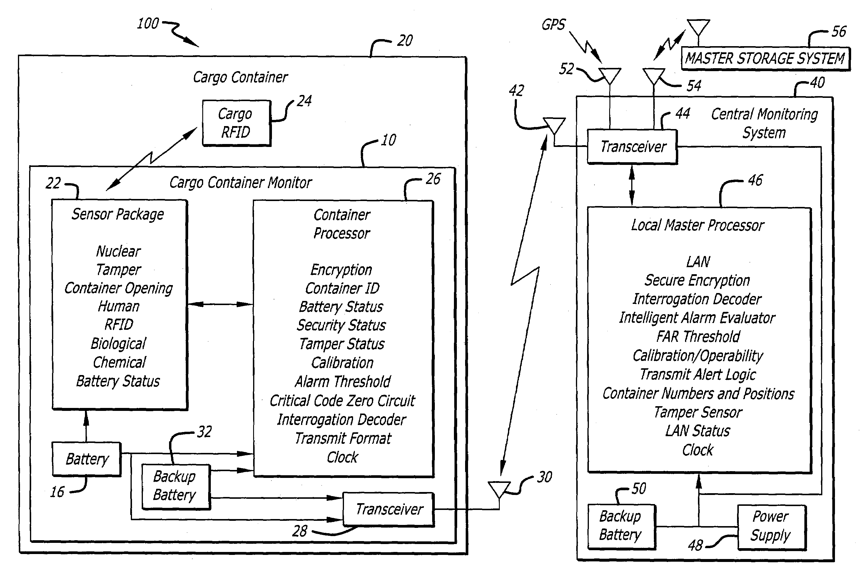
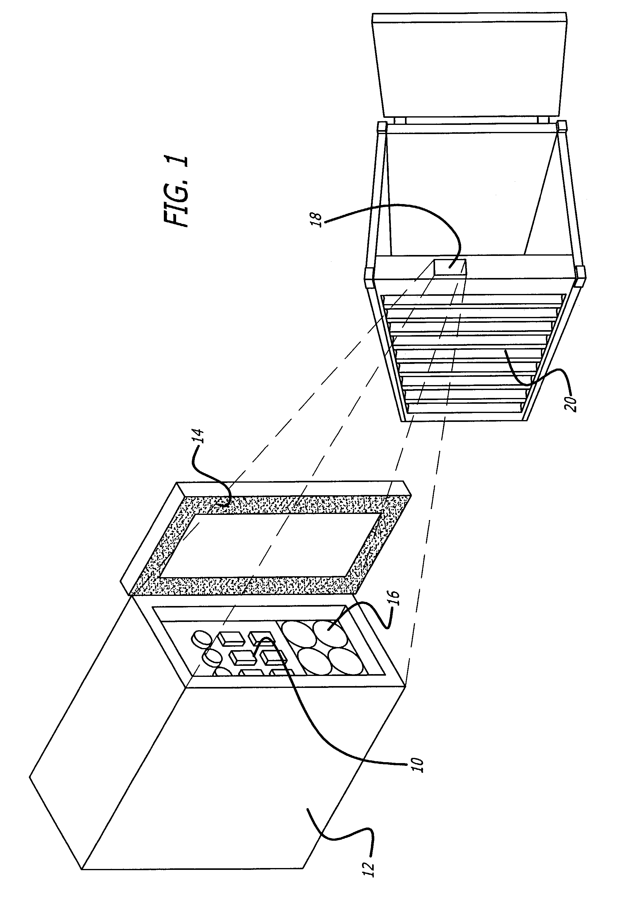
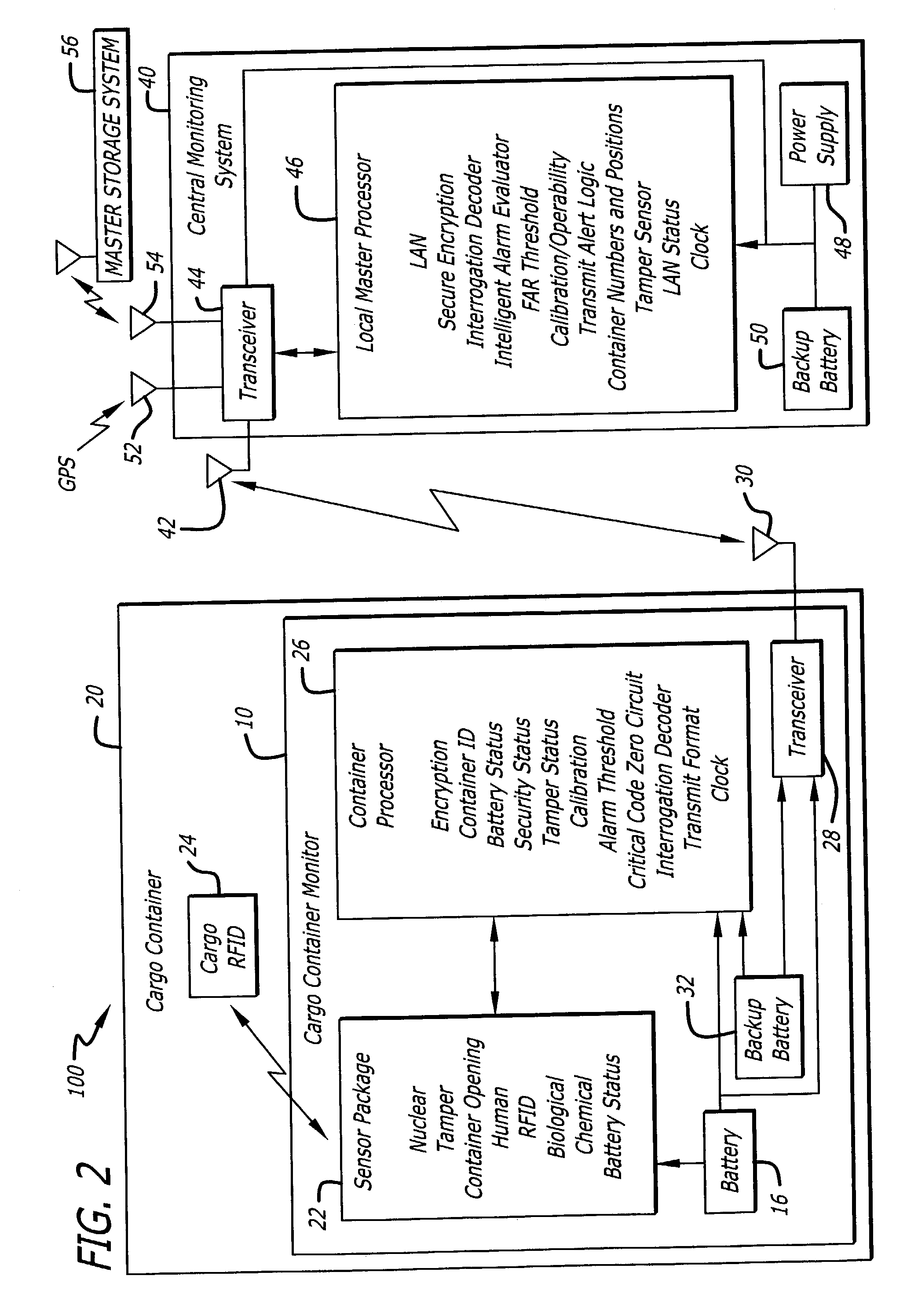
[0017]Existing detectors are large and expensive primarily because they are required to detect the presence of explosives in a short time (about 10–20 seconds) with low probability of false alarm. This invention relies on the availability of a longer integration time (hours to days), which allows the use of small inexpensive detectors for the various...


PUM


Abstract

A system and method for monitoring a cargo container. The novel system (100) includes a sensor module (10) mounted in each target area (20) and a central monitoring system (40). Each sensor module (10) includes one or more sensors (22) and a transceiver (28) for transmitting data from the sensors to the central monitoring system (40). The central monitoring system (40) includes a transceiver (44) for receiving the data from all sensor modules (10) and a local master processor (46) for processing and analyzing the data. In the preferred embodiment, each transceiver (28) is capable of receiving and retransmitting signals of other sensor modules to relay signals of a particular sensor module (10) in a daisy chain fashion to and from the central monitoring system (40).

Description

BACKGROUND OF THE INVENTION[0001]1. Field of the Invention[0002]The present invention relates to sensors. More specifically, the present invention relates to systems for detecting hazardous materials.[0003]2. Description of the Related Art[0004]Recent world events have revealed the need for early detection and interdiction of materials that can be used to construct weapons of mass destruction, i.e., explosives, biological and chemical agents, and nuclear materials. At the present time, the only comprehensive means of detection are random searches for which the probability of detection is small due to the limited sample set. Point solutions exist for the detection of various materials, such as an explosives detection unit. The cost, size, and limited throughput of these units, however, have limited their deployment.[0005]Furthermore, inspections typically occur when materials are already at a vulnerable destination and the process of inspection may trigger detonation. Much of the rec...

Claims


Application Information

Patent Timeline
Patent Type & Authority Patents(United States)
IPC IPC(8): G08B1/00G06Q10/08G08B25/00G08B25/10
CPCG06Q10/08G08B25/10G08B25/009G08B25/004
Inventor CANICH, DAVID J.CROUCH, DAVID D.GALLIVAN, JAMES R.KARLSON, ROBERT E.KATO, KEITH G.SAR, DAVID R.STARBUCK, PHILIP D.
Owner RAYTHEON CO
Why Eureka
Try Eureka