Closing unit for injection molding machine

a technology of injection molding machine and closing unit, which is applied in the field of closing unit of injection molding machine, can solve the problems of large space occupation, high oil consumption, and the stroke of the hydraulic cylinder must be relatively larg

Inactive Publication Date: 2001-04-03
HUSKY INJECTION MOLDING SYST LTD
View PDF24 Cites 41 Cited by
  • Summary
  • Abstract
  • Description
  • Claims
  • Application Information

AI Technical Summary

Problems solved by technology

Since the four hydraulic cylinders at the same time perform a locking function and a displacement function, they must be both of large cross section and have a large stroke and they therefore take up a relatively large amount of space.
The four relatively large hydraulic cylinders accordingly substantially impede access to the injection unit and furthermore have a very high consumption of oil.
If the closing unit, however, is to be used with injection molds of different length, the stroke of the hydraulic cylinders must be relatively large and the closing unit of FIG. 53B has substantially the same disadvantages as the aforementioned closing unit of FIG. 56.
A large flank clearance, however, also has substantial disadvantages.
Thus, for example, the operating stroke of the force cylinders is increased thereby, and thus the consumption of energy by the closing unit.

Method used


Image

  • Closing unit for injection molding machine
  • Closing unit for injection molding machine
  • Closing unit for injection molding machine

Examples


Embodiment Construction

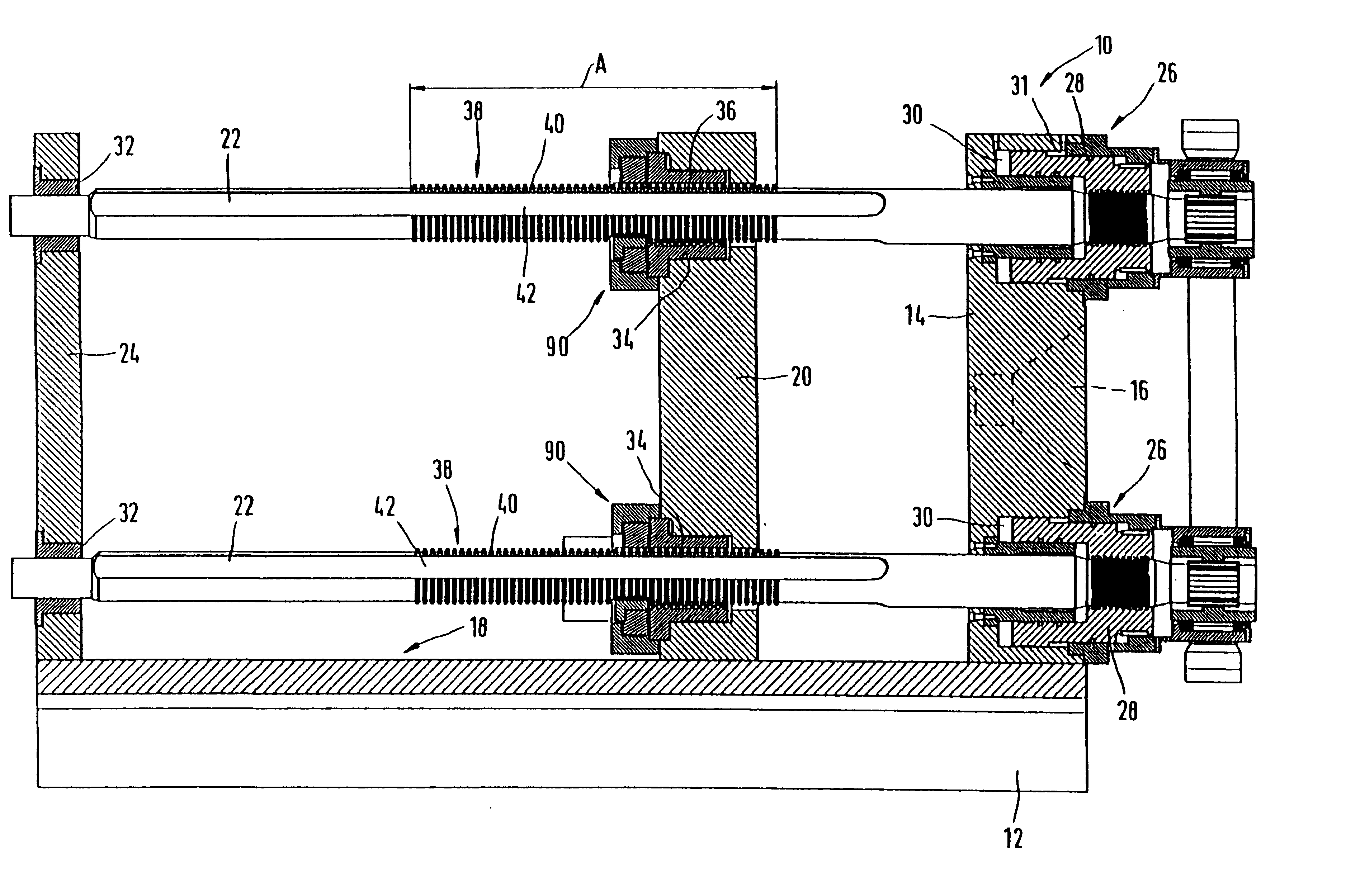
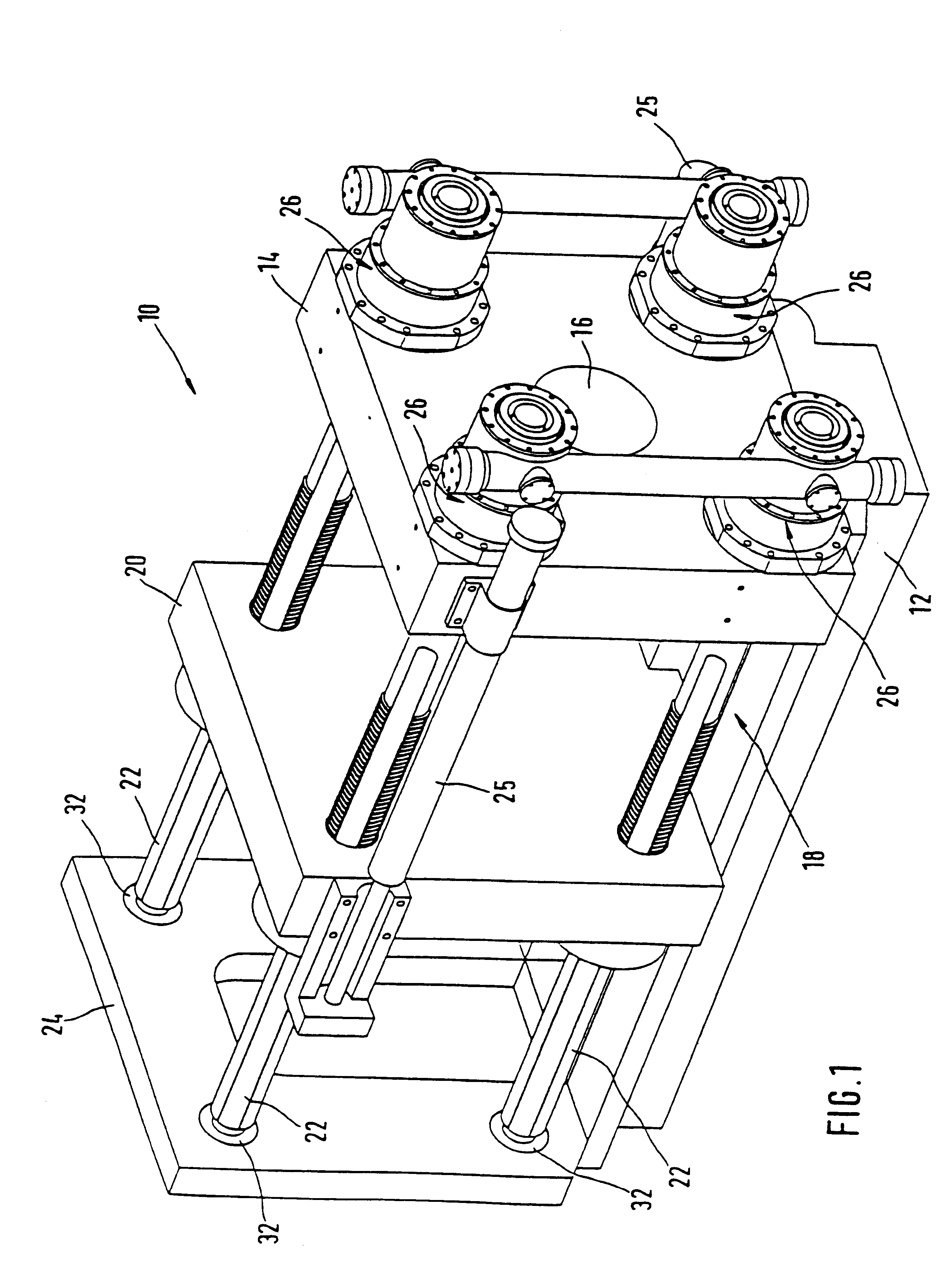
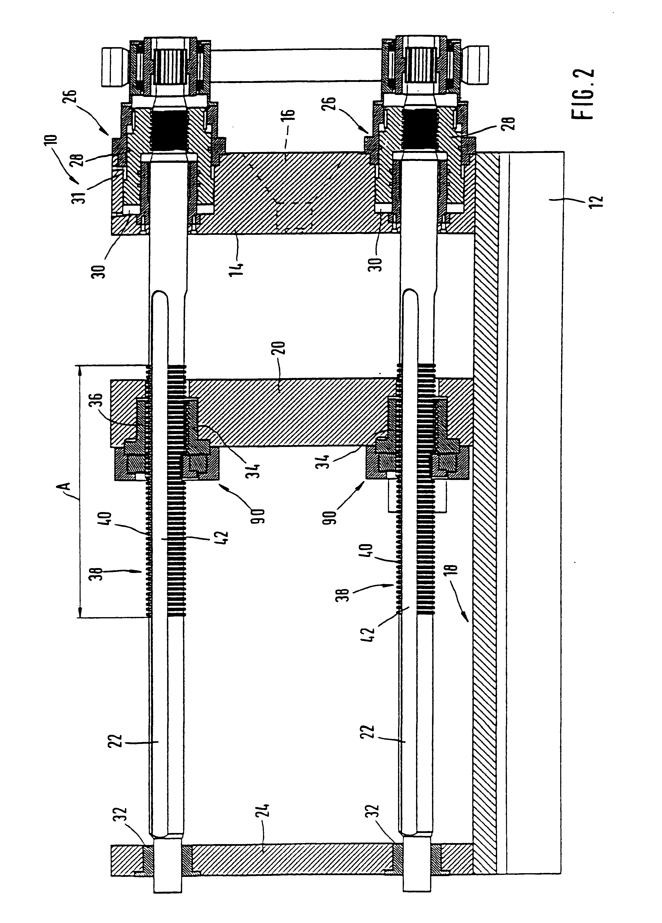
The general construction of a closing unit 10 in accordance with the invention will be explained with reference to FIGS. 1 and 2. An injection plate 14 having a central injection opening 16 is rigidly mounted on a base 12. The base 12 forms a guide bed 18 for a movable closure plate 20. The complementary halves of an injection mold (not shown) are clamped to injection plate 14 and closure plate 20. The movable closure plate 20 is displaceable via an actuating device which comprises, for instance, two laterally arranged displacement cylinders 25 movable between injection plate 14 and an end plate 24. It is guided in this connection in the base 12. The displacement cylinders 25 accordingly open and close the complementary halves of the injection mold by displacement of the closure plate 20 relative to the injection plate 14. The housing of the displacement cylinders 25 is fastened in each case on the stationary injection plate 14 so that both displacement cylinders 25 have a rigid hyd...


PUM

PropertyMeasurementUnit
angleaaaaaaaaaa
angleaaaaaaaaaa
angleaaaaaaaaaa

Abstract

A closing unit for an injection moulding machine has a movable closing die and a fixed matching die designed as clamping dies for an injection mould, as well as several hydraulic cylinders mounted on the fixed matching die to apply a closing force. A servo-drive allows the drawbars to swivel around their longitudinal axes up to a first and second angular position. A first locking device arranged on the drawbars along a first section A of the drawbars co-operates with second locking device arranged on the movable closing die. In the first angular position of the drawbars, the locking devices allow the movable closing die to move axially with respect to the drawbars, and in a second angular position of the drawbars they transmit the required closing force.

Description

1. Field of the InventionThe present invention relates to a closing unit for an injection molding machine.2. Related ArtThe closing unit of an injection molding machine receives the injection mold. It carries out the movements necessary for the closing and opening of the injection mold and produces the forces necessary for the locking and opening of the injection mold. The main components of each closing unit are a stationary plate on the injection side (hereinafter referred to as the injection plate), a movable closure plate, as well as a locking device. One part of the injection mold is clamped on the stationary injection plate while the complementary part of the injection mold is clamped on the movable closure plate. By locking device there is to be understood the device which, upon the injection and further pressing, produces the necessary closing force for keeping the injection mold closed.Both mechanical locking devices with lever mechanisms and hydraulic locking devices with ...

Claims


Application Information

Patent Timeline
Patent Type & Authority Patents(United States)
IPC IPC(8): B29C45/67B22D17/26
CPCB29C45/6707
Inventor MAILLIET, PIERREMAILLIET, MONIQUE
Owner HUSKY INJECTION MOLDING SYST LTD
Why Eureka
Try Eureka