Apparatus for bracing vertebrae

Inactive Publication Date: 2001-04-10
STRYKER TRAUMA GMBH
View PDF13 Cites 99 Cited by
  • Summary
  • Abstract
  • Description
  • Claims
  • Application Information

AI Technical Summary

Problems solved by technology

Again, the devices last mentioned require separate means for repositioning, thus being suited to maintain a repositioned condition, but not suited to perform repositionin

Method used


Image

  • Apparatus for bracing vertebrae
  • Apparatus for bracing vertebrae
  • Apparatus for bracing vertebrae

Examples


Example

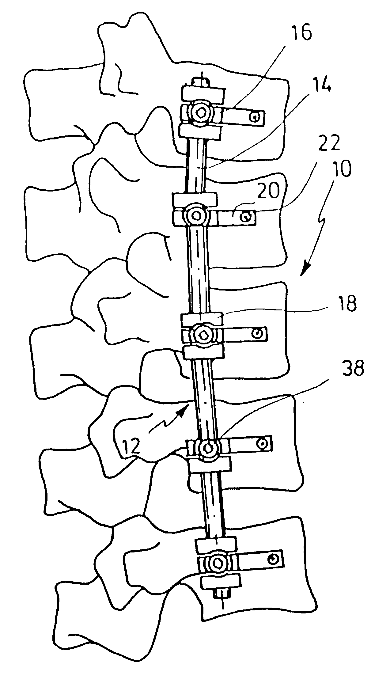
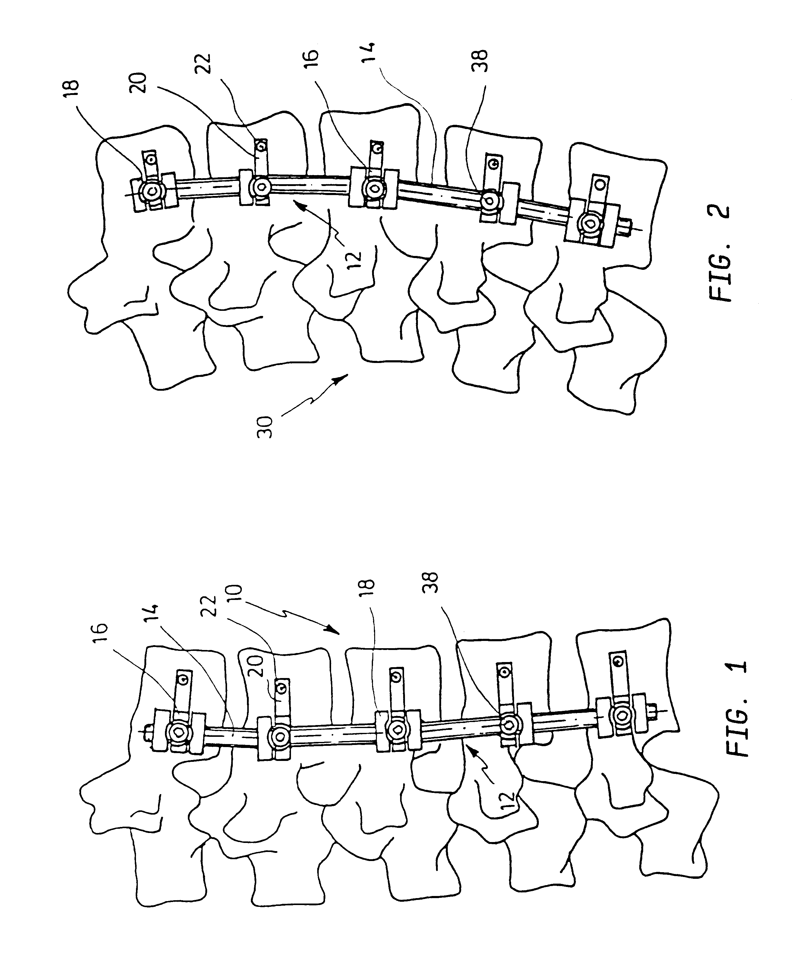
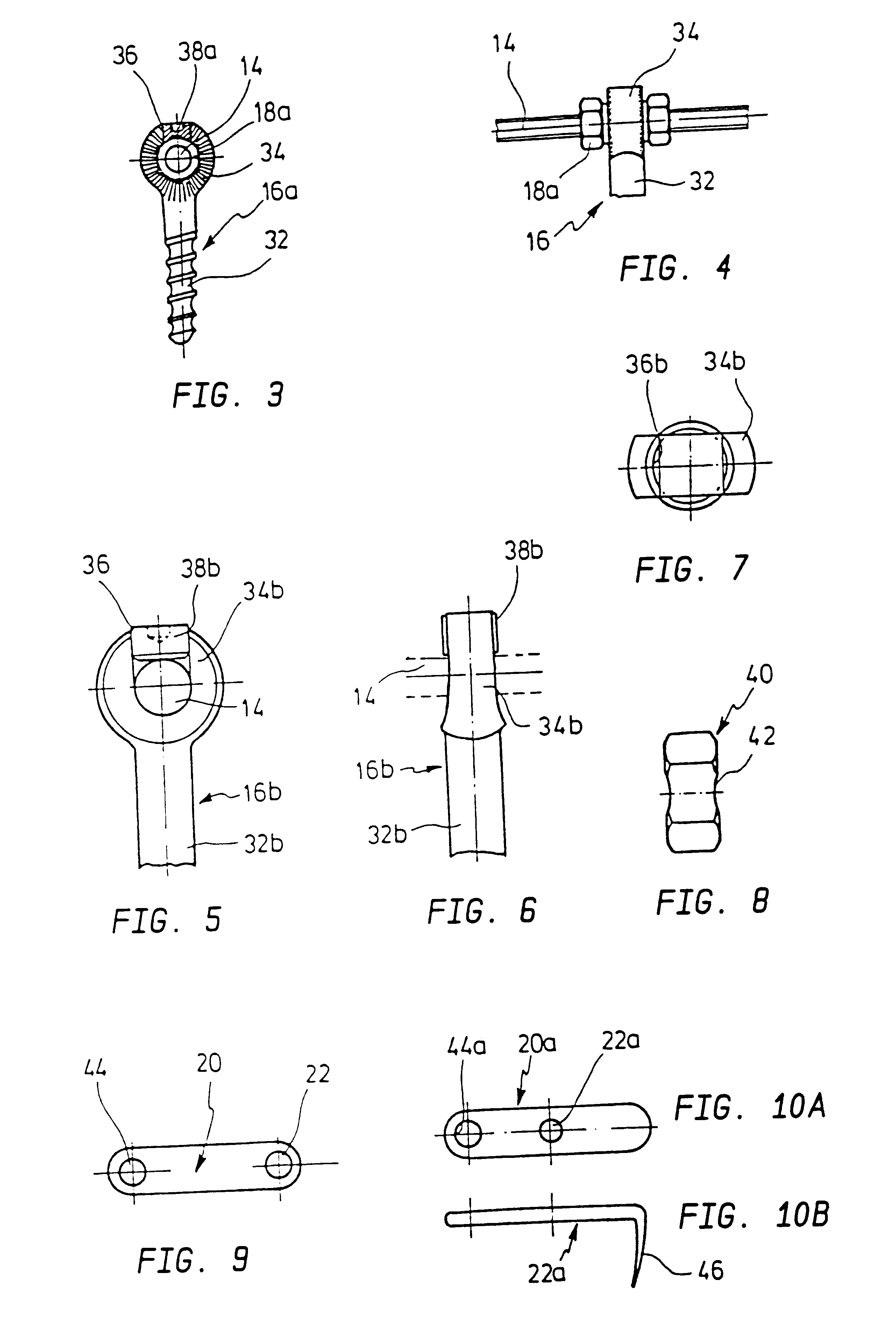
FIG. 1 shows a bent spine portion 10 wherein the individual vertebras shall be distracted by means of a distracting system 12. The system comprises a relatively stiff threaded rod 14 having a diameter of 6 to 9 mm, preferably 7 to 8 mm. It cooperates with an individual pedicel screw 16 screwed in the vertebras. Details of the screws are shown in the following figures. The threaded rod 14 is received in slots of the pedicel screw heads 16 and a plurality of adjusting nuts 18 is disposed on the rod 14, at least one nut each for a pedicel screw 16. Stabilizing latches 20 cooperate with the pedicel screws, which latches include a hole 22 in a distance from the pedicle screw to receive a spongise screw screwed in the vertebra. By means of the adjusting nut 18 a pedicel screw screwed in the vertebra may be displaced relative to the rod 14 and thus with respect to the vertebra receiving the screw. By means of the adjusting nuts 18 the vertebrae of the portion 10 may be thus adjusted to acc...


PUM


Abstract

An apparatus for bracing a plurality of vertebrae of the human spine has at least two pedicle screws, each having an annular head with an opening therewithin and including a slot therewithin. Each slot extends into the corresponding opening and includes internal threaded portions. A securing screw to be screwed in each slot is provided. A relatively stiff threaded rod is also provided and is to be inserted into the opening in the head of each of the pedicle screws and to be secured by the securing screws. Adjusting nuts are screwed on the rod and at least one cooperates with each head.

Description

1. Field of the InventionKnown supporting means operate with so-called lamina hooks which are disposed on a threaded rod. A compressing means is disclosed in British patent 2 131 300. A distracting means is disclosed in U.S. Pat. No. 4,383,438. The threaded rod bridges a plurality of vertebras and is not suited to act on vertebras which are disposed between the lamina hooks. The thread of the rod is used to fix the lamina hooks. Before using the supporting means a distraction or, respectively, compression has to be provided by means of an additional device.DESCRIPTION OF THE PRIOR ARTGerman 90 06 646 U1 discloses an apparatus in which a lamina hook is replaced by a clamp-shaped holding member having a pair of legs of which one can be bent with respect to the other. Thereby the giapophysis of the vertebras may be used as anchoring points for the compressing and distracting apparatus.German 88 02 112 U1 teaches a supporting device for the human spine, according to which the so-called ...

Claims


Application Information

Patent Timeline
IPC IPC(8): A61B17/70A61B17/56A61F2/44A61B17/58A61B17/60
CPCA61B17/7008A61B17/7032A61B17/7037A61B17/7038
Inventor METZ-STAVENHAGEN, PETER
Owner STRYKER TRAUMA GMBH
Why Eureka
Try Eureka