Lighting assembly for multiple fluorescent lamps

a technology for fluorescent lamps and lighting assemblies, which is applied in the direction of lighting support devices, light source combinations, coupling device connections, etc., can solve the problem of increasing the manufacturing cost of lighting assemblies

Inactive Publication Date: 2001-04-17
THE WHITAKER CORP
View PDF15 Cites 106 Cited by
  • Summary
  • Abstract
  • Description
  • Claims
  • Application Information

AI Technical Summary

Problems solved by technology

When a defective ballast is replaced, often on a trial and error basis, these wires must be disconnected and reconnected.
Installation and m

Method used


Image

  • Lighting assembly for multiple fluorescent lamps
  • Lighting assembly for multiple fluorescent lamps
  • Lighting assembly for multiple fluorescent lamps

Examples


second embodiment

this invention is shown in FIGS. 9 and 10. This embodiment uses a three-lamp ballast lampholder subassembly 104 and a three-lamp lampholder connector 150. The three-lamp ballast lampholder subassembly 104 includes a ballast circuit for use in a three-lamp lighting fixture, but in most other respects is constructed in the same manner as the four-lamp version. The principal difference is that the three-lamp ballast lampholder subassembly 104 includes a wire 105 that connects the three-lamp ballast lampholder subassembly 104 to the three-lamp lampholder connector 150 located at the opposite end of the fluorescent lamps in a three-lamp lighting fixture. This wire 105 is connected to the ballast lampholder subassembly 104 in substantially the same manner as to the lampholder connector 150, and attachment of this wire will be discussed with reference to the lampholder connector 150. The three-lamp lighting fixture thus can operate in much the same manner as that described in U.S. Pat. No....


PUM


Abstract

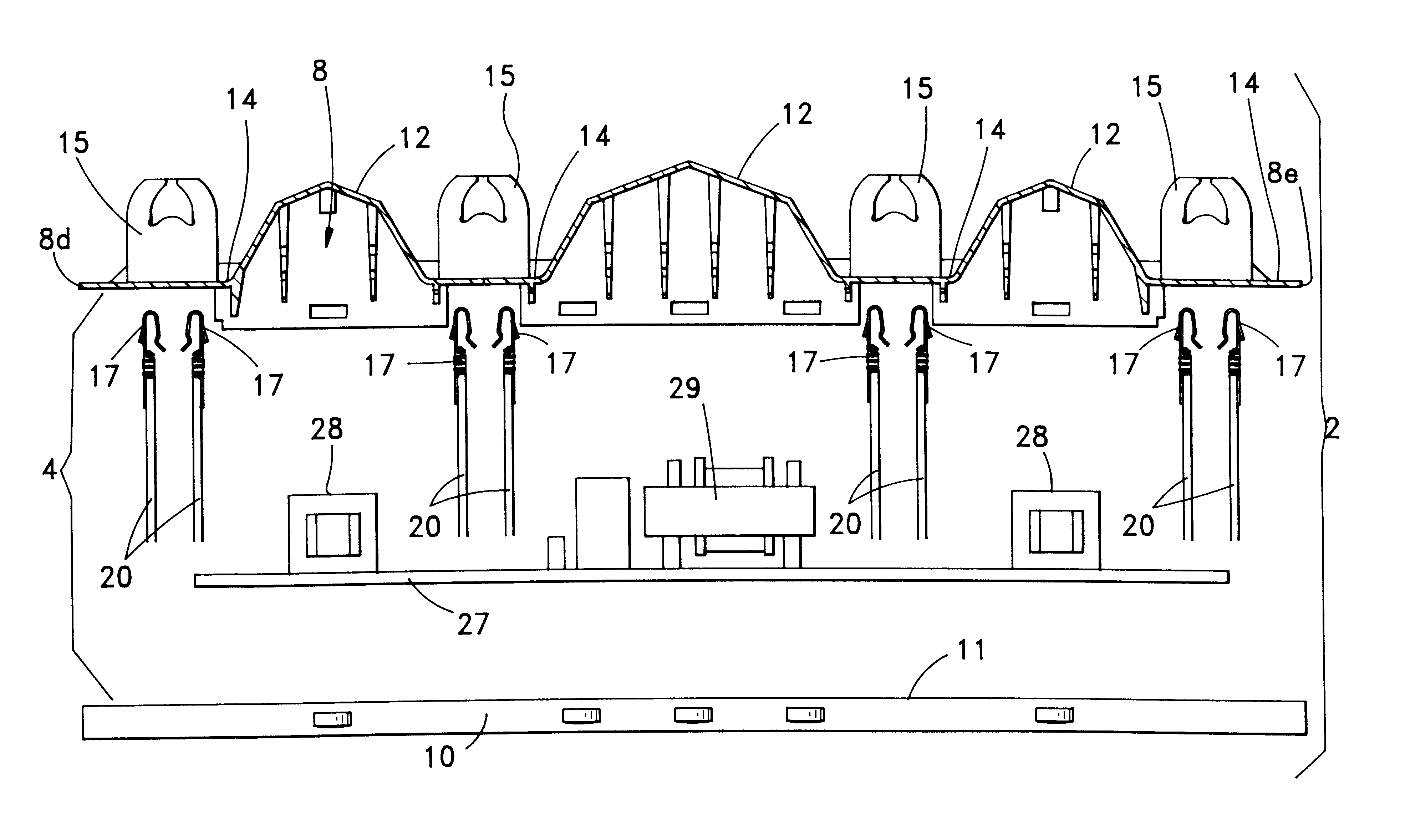
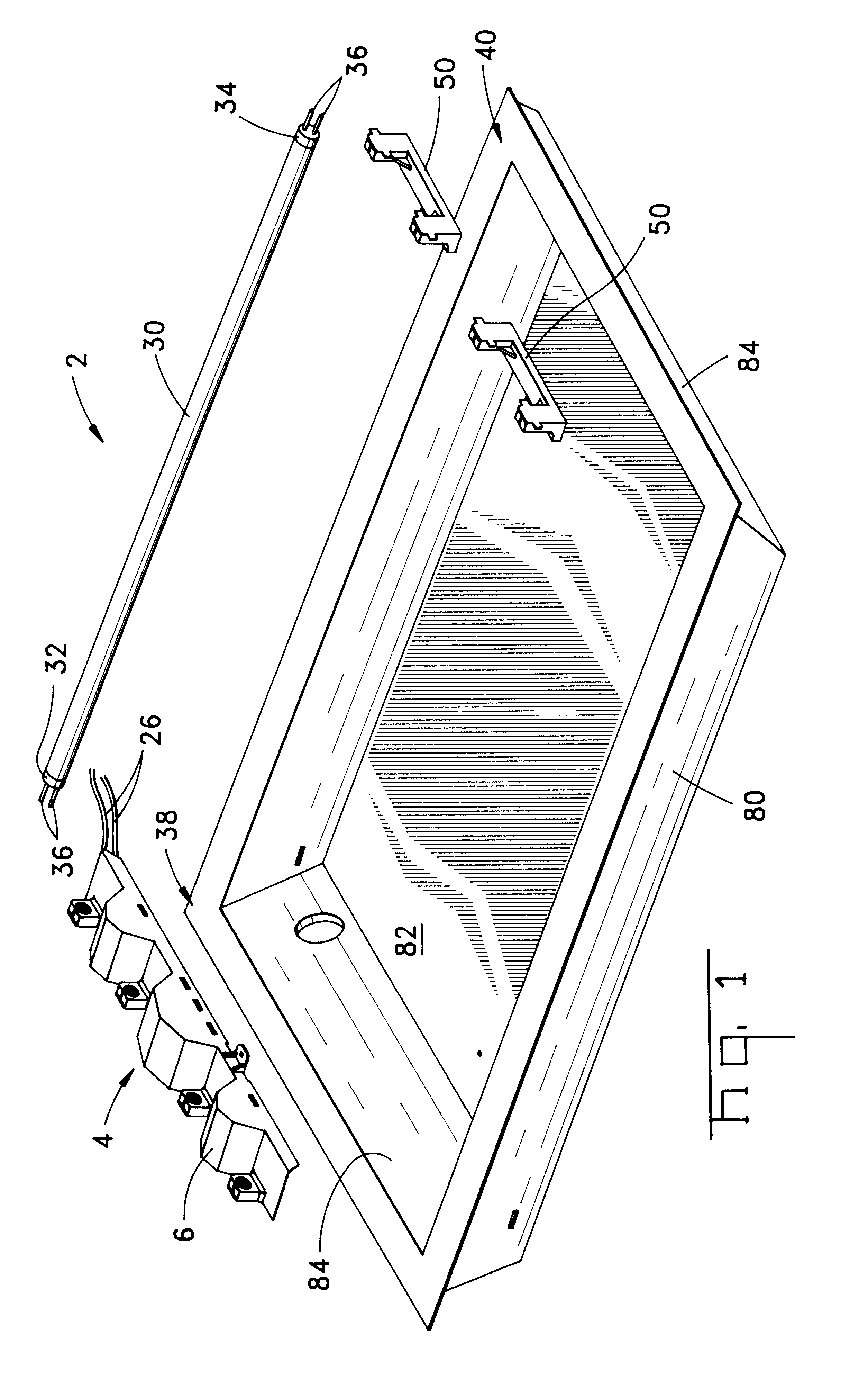
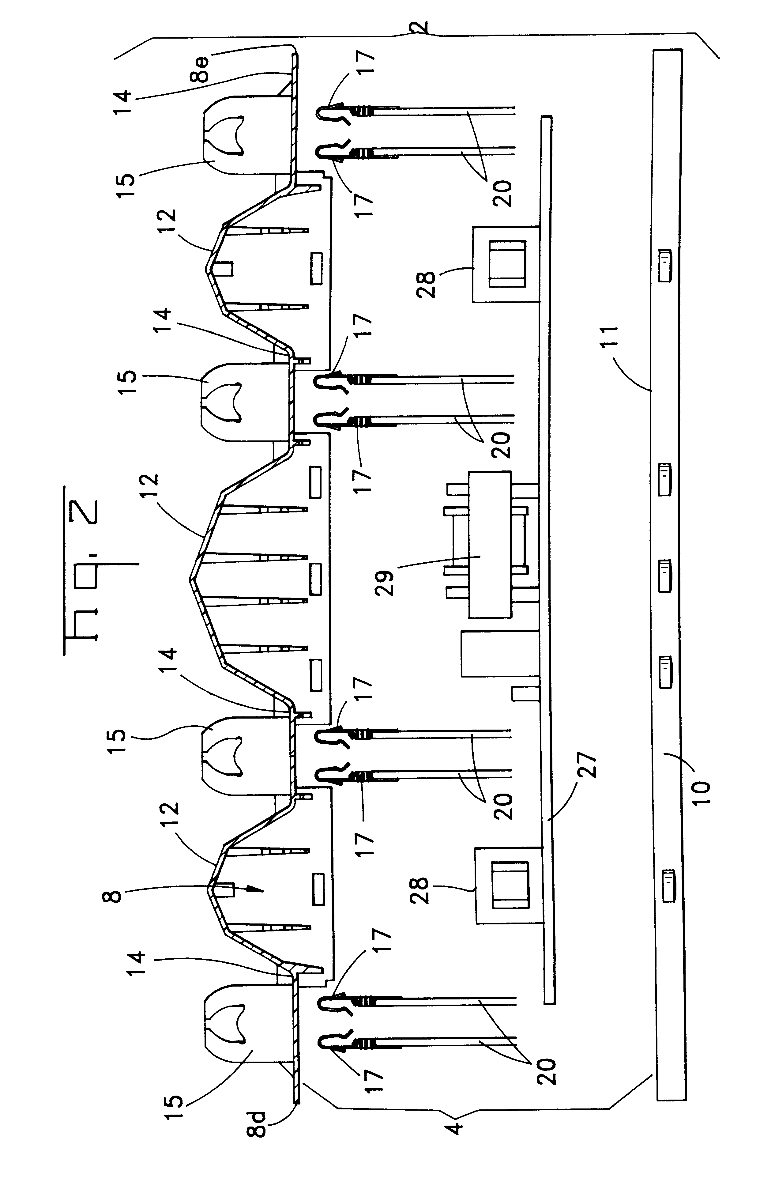
A fluorescent lighting assembly (2) includes a ballast lampholder subassembly (4) located at one end of a troffer (80) and at least one lampholder connector (50) located at the opposite end. The ballast lampholder subassembly (4) includes ballast circuitry connected to fluorescent lamp terminals (17) all positioned within a ballast lampholder housing (6). A molded ballast lampholder cover (8) encloses three sides of the ballast lampholder subassembly and a stamped metal plate forms the ballast lampholder base (10), with the ballast circuitry located on a circuit board (27) positioned on the interior surface of the base. Integrally molded lampholders (15) extend from channels (14) on the cover (8) and are positioned between larger enclosure sections (12) which provide space for larger ballast components. Fluorescent lamp terminals (17) are inserted from the interior of the cover into cavities (16) in lampholders (15), and lead wires connect the terminals to the printed circuit board. Lampholder connectors (50) including integrally molded lampholders (51) are located at the opposite end of the fluorescent lighting assembly (2).

Description

1. Field of the InventionThis invention is related to lighting assemblies and is more particularly related to fluorescent lighting assemblies using electronic ballasts. More particularly, this invention is related to a fluorescent subassembly or lampholder including ballast components and integral fluorescent sockets.2. Description of the Prior ArtConventional ballasts used in overhead troffers or luminaires include lamps, ballasts and socket subassemblies or lampholders. The ballast or ballasts are mounted at the center of the troffer and attached to the top of the troffer. Wires extend from the ballast or ballasts to sockets located at opposite ends of the troffer. For a four lamp assembly, wires must be connected to sockets at both ends of the four lamps. When a defective ballast is replaced, often on a trial and error basis, these wires must be disconnected and reconnected. Installation and maintenance of conventional lighting assemblies is therefor time consuming and the manufa...

Claims


Application Information

Patent Timeline
IPC IPC(8): H01R33/08H01R33/05H01R25/00H01R25/16
CPCF21V19/008F21V23/02H01R33/0818H01R25/16F21Y2103/00F21Y2113/00
Inventor ALTMAN, BARRY EDDINGTONTURNER, JOHN FRANCISKETELSLEGER, KIMBERLY ANN
Owner THE WHITAKER CORP
Why Eureka
Try Eureka