
Field synchronization system and technique

a field synchronization and field technology, applied in the field of field synchronization system and technique, can solve the problem that no specific apparatus has been established

Inactive Publication Date: 2001-05-01
UNITED STATES OF AMERICA THE AS REPRESENTED BY THE SEC OF THE ARMY
View PDF3 Cites 3 Cited by
  • Summary
  • Abstract
  • Description
  • Claims
  • Application Information

AI Technical Summary

Problems solved by technology

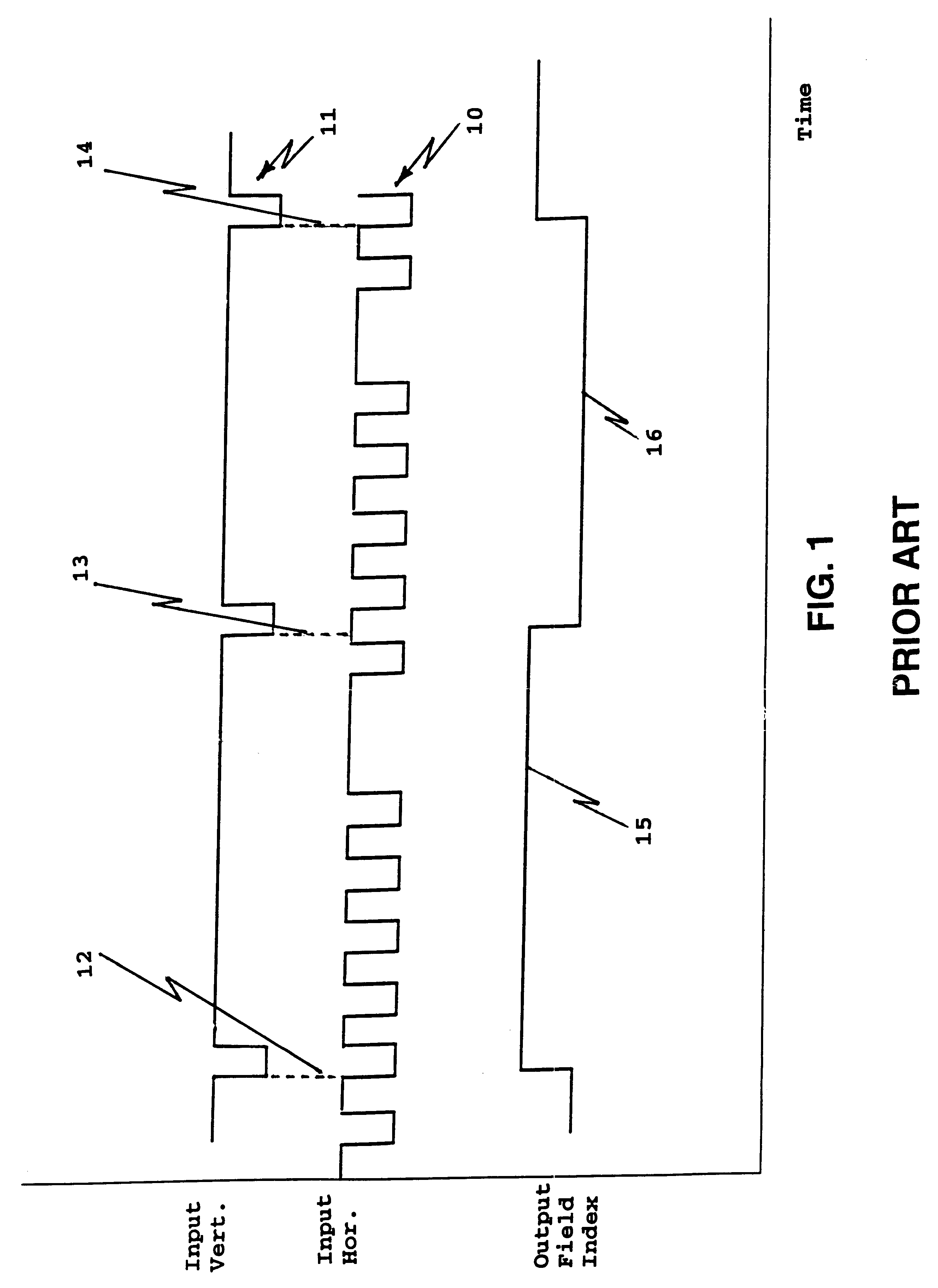
A problem occurs in the prior art when the digital data inputs to the field circuitry does not follow the SMPTE Standard 244M known in the Prior Art.
Many FLIR sensors output their own field index but do not follow the accepted protocol with respect to the falling edges of the horizontal and vertical synchronization signals.
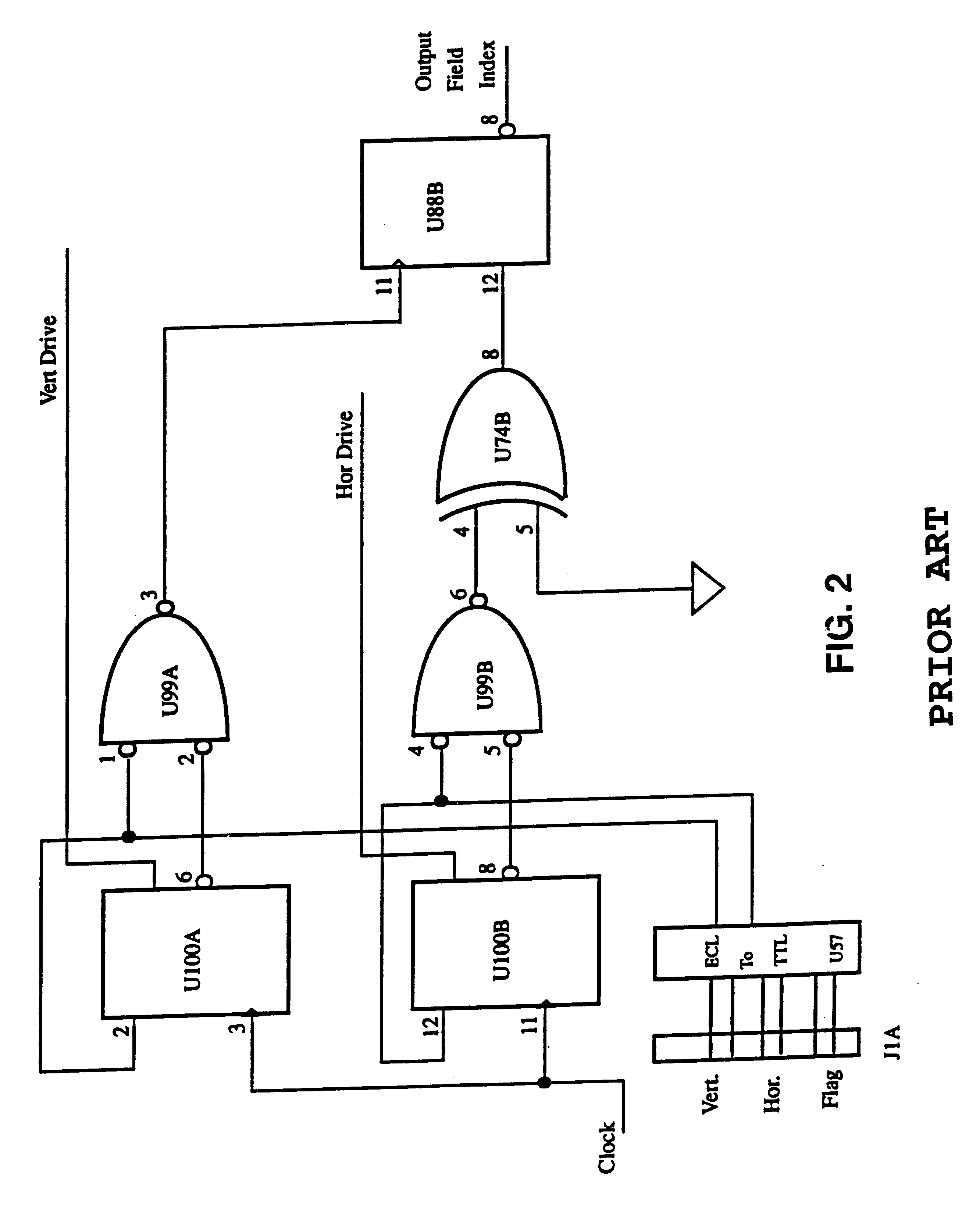
While the prior art has reported using field detect circuits, none have established a basis for a specific apparatus that is dedicated to the task of resolving the particular problem at hand.

Method used


Image

  • Field synchronization system and technique
  • Field synchronization system and technique
  • Field synchronization system and technique

Examples


Embodiment Construction

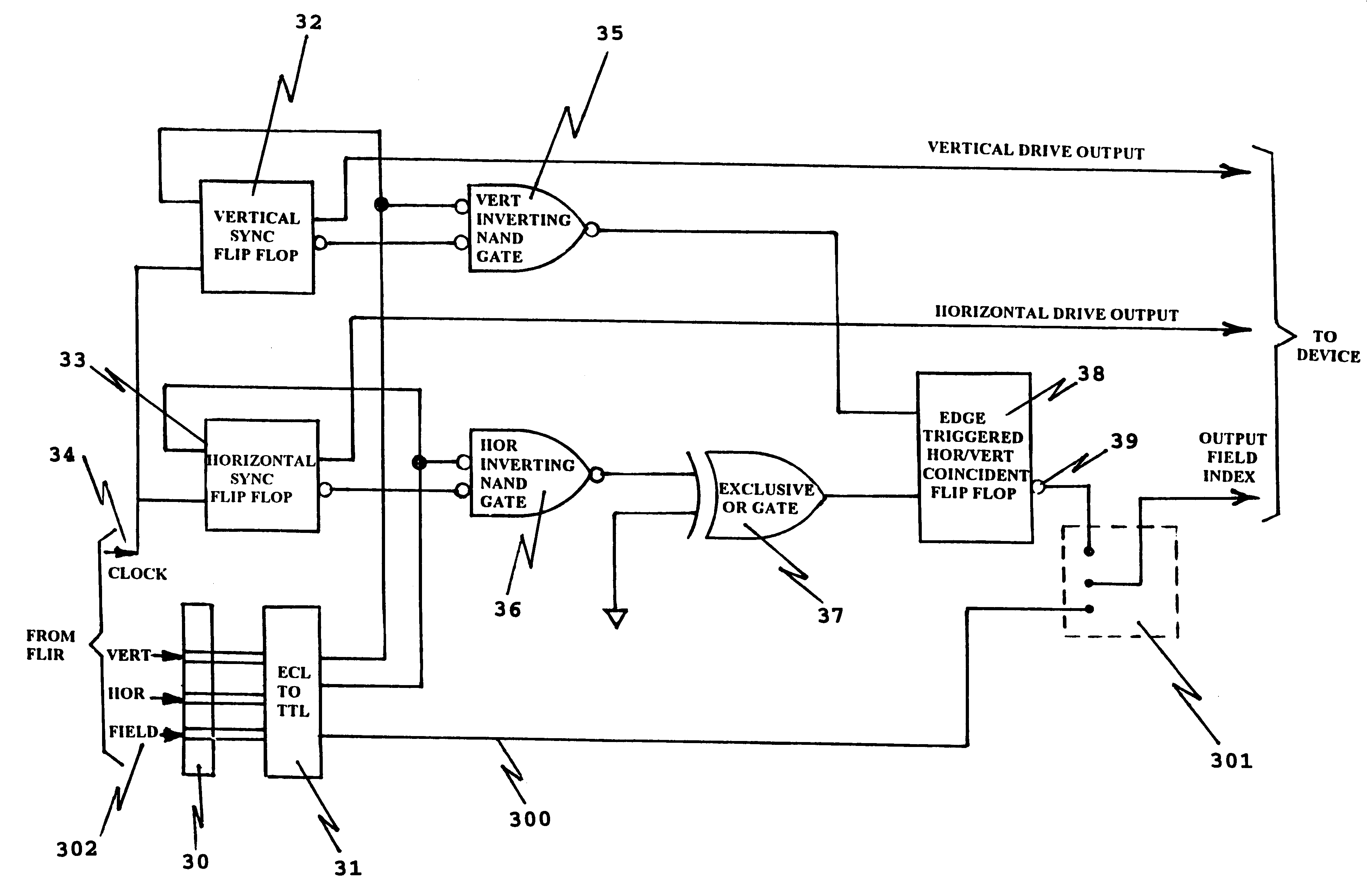
A prior art technical standard by the Society of Motion Picture and Television Engineers (SMPTE) is recognized as a standard for timing protocol which is utilized in the prior art field detect circuits. The SMPTE standard 244M digital timing protocol utilizes a TTL voltage level vertical synchronization signal operating at a 60 Hz interval rate to indicate the start of each field of 30 Hz rate digital data. Normal timing protocol dictates that the raising edge of a vertical sync occur every 1 / 60 sec (60 Hz) to indicate the start of a new field. At the time the raising edge of the vertical sync pulse occurs, the 30 Hz signal of the field sync goes high and remains high for a period of 1 / 60 of a second during which time the data being transferred is defined as field one. 1 / 60 of a second after the raising edge of the field sync has occurred the signal goes low. While the field sync is low the data that is transferred belongs in field two. The horizontal pulse indicate the start of a n...


PUM


Abstract

A field synchronization system of a field detect circuit adaptable for use with non-standard output digital data of forward looking infrared (FLIR) sensors. Timing signals and digital data from a FLIR sensor are utilized and there is outputted a vertical and horizontal signal output. A bypass circuit allows for the optional bypass of frame grabber generated field index circuitry so that an external field index signal is utilized.

Description

1. Field of the InventionThe present invention generally relates to a field synchronization system and technique and more specifically, to a field synchronization system and technique of a field detect circuit adaptable for use with non-standard output digital data ports of forward looking infrared (FLIR) sensors.2. Description of Prior ArtTelevision is the transmission of scenes, either still or in motion, by electrical means. It is necessary to break up the scene into minute elements and utilize these elements in an orderly sequence. This process is called scanning, a type of which is somewhat similar to the process of reading a text line-by-line (or row of data) from a printed page (called interlacing). Because of the physical principles involved, there is a relationship between brightness and the rate of scanning: brightness going down with increase scanning rate. To provide a true and realistic feeling of motion to all actions displayed, it is necessary to present a number of p...

Claims


Application Information

Patent Timeline
Patent Type & Authority Patents(United States)
IPC IPC(8): H04N5/08H04N5/33H04N5/10
CPCH04N5/10H04N5/33H04N23/20
Inventor WEBB, CURTIS M.
Owner UNITED STATES OF AMERICA THE AS REPRESENTED BY THE SEC OF THE ARMY
Learn More