Cable connector with improved grounding arrangement

a cable connector and grounding arrangement technology, applied in the direction of coupling device connection, electrical apparatus, coupling protective earth/shielding arrangement, etc., can solve the problems of reducing the shielding effect of the shielding mechanism, adversely affecting the reliability of signal transmission, and disrupting signal transmission of a conventional cable connector. achieve the effect of excellent configuration

Inactive Publication Date: 2001-05-08
HON HAI PRECISION IND CO LTD
View PDF3 Cites 0 Cited by
  • Summary
  • Abstract
  • Description
  • Claims
  • Application Information

AI Technical Summary

Benefits of technology

The first and second grounding tabs are formed on opposite lateral edges of the first and second shells and assembled to the corresponding shoulders of the housing, moreover, a pair of cutout is defined in middle of the second shell responding to the position

Problems solved by technology

Signal transmission of a conventional cable connector is often disrupted by electromagnetic interference.
Thus, the grounding path will form open circuit or break off thereby decreasing the shielding effect of the shielding mechanism and adversely

Method used


Image

  • Cable connector with improved grounding arrangement
  • Cable connector with improved grounding arrangement
  • Cable connector with improved grounding arrangement

Examples


Embodiment Construction

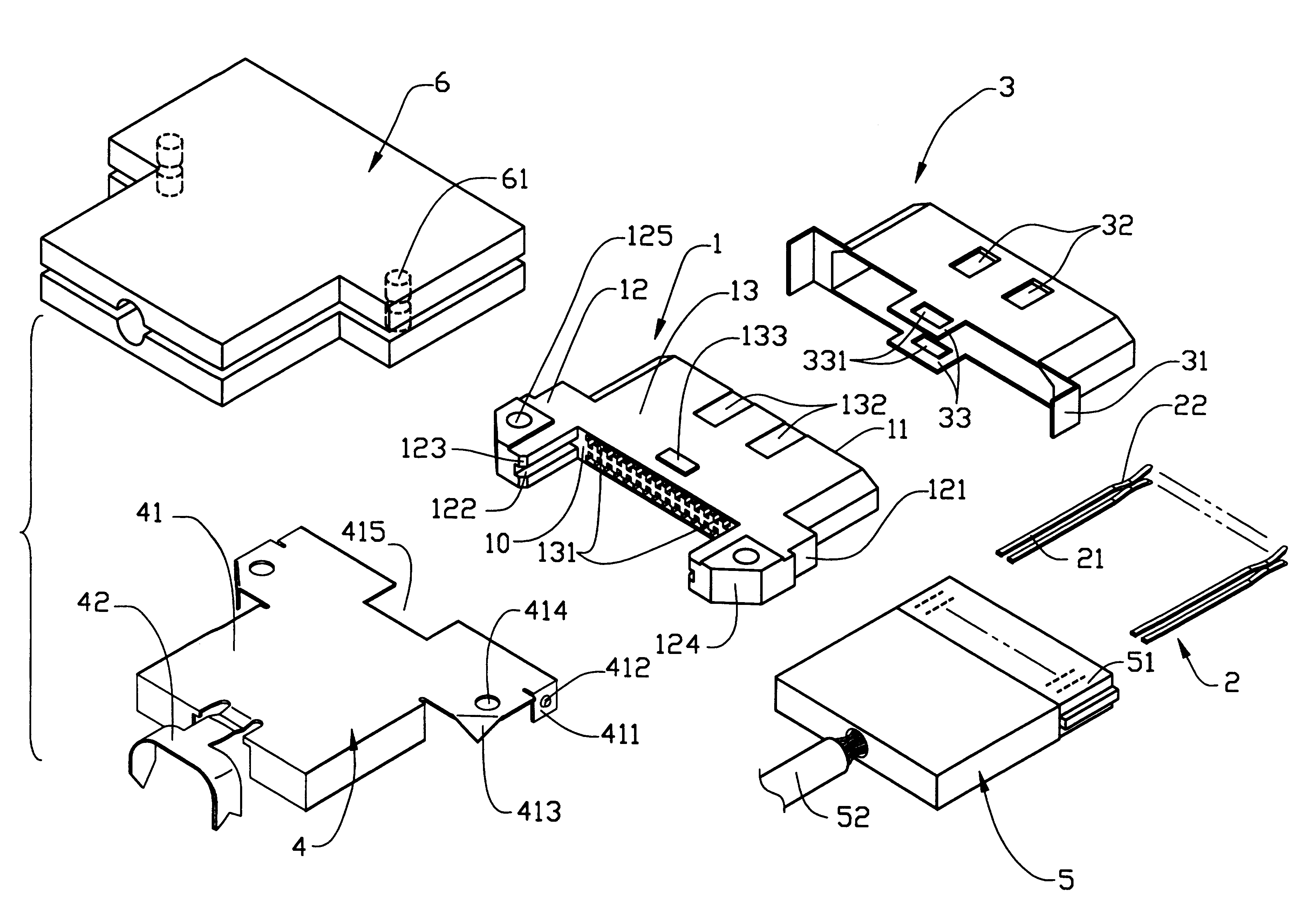
Referring to FIG. 3, a cable connector in accordance with the present invention comprises a dielectric housing 1 receiving a plurality of contacts 2 therein, a shielding mechanism including a first shell 3 and a second shell 4 for enclosing the housing 1 therein, a module 5 including a circuit board 51 for electrically connecting with the housing 1, and a dielectric jacket 6 for enclosing the cable connector. The housing 1 has a mating surface 11, a connecting surface 10, a base 13 between the mating surface 11 and the connecting surface 10, and a frame 12 outwardly extending from opposite sides of the connecting surface 11 in a longitudinal direction. The frame 12 is U-shaped and forms a pair of positioning portions 121 for engaging with the first and second shells 3, 4. A pair of guiding grooves 122 is defined in opposite inner side surfaces of the positioning portion 121 for guiding the circuit board 51 of the module 5 into the housing 1. A pair of first diagonal faces 123 is for...


PUM


Abstract

A cable connector with improved grounding arrangement for electrically connecting to a shielded cable comprises a dielectric housing receiving a number of contacts therein, a shielding mechanism consisting of a first shell and a second shell, a module including a circuit board, and a dielectric shell enclosing the cable connector. The housing forms a frame comprising a pair of step-like shoulders and a pair of diagonal faces. The first and second shells form a pair of first and second grounding tabs, respectively, for engaging with the corresponding shoulders of the housing. The first grounding tabs overlap on the corresponding second grounding tabs thereby forming a grounding path through grounding wires of the cable terminated to the cable connector, the second shell, the first shell and a shield of a mating connector therethrough. The first shell also has a pair of positioning tabs extending from middle portions of edges of upper and lower surfaces thereof. Each positioning tab defines a latching aperture therein for securing corresponding projection formed on the housing. Therefore, the shielding mechanism provides the cable connector with reliable grounding capabilities when the cable connector undergoes a bending test due to the provision of middle cutouts of the second shell and the middle grounding tabs of the first shell.

Description

BACKGROUND OF THE INVENTIONThe present invention relates to a cable connector, and particularly to a cable connector with improved grounding arrangement for electrically engaging with a shielded cable.Signal transmission of a conventional cable connector is often disrupted by electromagnetic interference. Conventional cable connectors usually have a grounding or shielding mechanism for providing protection from electromagnetic interference. Pertinent examples are disclosed in Taiwan Patent Application Nos. 82101300, 821109498 and 83200965.Referring to FIGS. 1 and 2, a shielding mechanism of a conventional cable connector comprises a first shell 3' and a second shell 4'. The first shell 3' forms two pairs of latching tabs 32' on opposite edges thereof. Each latching tab 32' defines an aperture therein for engaging with corresponding first projections 16' formed on a dielectric housing 1' thereby fixing the first shell 3' to the housing 1'. The second shell 4' forms positioning plates...

Claims


Application Information

Patent Timeline
IPC IPC(8): H01R13/66H01R13/658
CPCH01R13/65802H01R13/6658H01R13/6582H01R13/6593
Inventor LAI, CHIN-TE
Owner HON HAI PRECISION IND CO LTD
Why Eureka
Try Eureka