Dynamic expression editor

a dynamic expression and editor technology, applied in the field of object-oriented programming systems and methods, can solve problems such as the inability of users to create composite objects

Inactive Publication Date: 2001-05-08
IBM CORP
View PDF4 Cites 21 Cited by
  • Summary
  • Abstract
  • Description
  • Claims
  • Application Information

AI Technical Summary

Benefits of technology

FIGS. 14 and 15 describe the process of defining an object element expression. FIG. 14 is a flow chart illustrating representative operations performed in defining the object element expression, and FIG. 15 is a depiction of one embodiment of a graphical user interface for the dynamic expression editor which can be used to define the object element expressions. FIG. 15 depicts one embodiment of the view 1502 of the expression elements. Although shown as a separate window from the composition editor window 502, the view 1502 is ordinarily advantageously placed in the fourth window portion 508 to allow the dynamic expression editor to be used in conjunction with the other features of the composition editor window 502. View 1502 presents a name associated with the hybrid object element to be created 1504. In the illustrated embodiment, the hybrid element 1504 to be defined is named "MYATT", and for purposes of example, will be defined as the sum of two attributes. Although useful for purposes of example, it is important to note that the present invention as described herein and as claimed is not limited to defining hybrid attributes from the attributes of combined objects. The present invention also allows hybrid attributes or methods to be created from any combination of methods, attributes, and operators.

Problems solved by technology

However, although existing tools allow new objects to be defined and edited, these tools do not allow the user to create composite objects by combining user-selectable elements of existing objects under user-definable rules.

Method used


Image

  • Dynamic expression editor
  • Dynamic expression editor
  • Dynamic expression editor

Examples


Embodiment Construction

In the following description, reference is made to the accompanying drawings which form a part hereof, and which is shown, by way of illustration, several embodiments of the present invention. It is understood that other embodiments may be utilized and structural changes may be made without departing from the scope of the present invention.

Hardware Environment

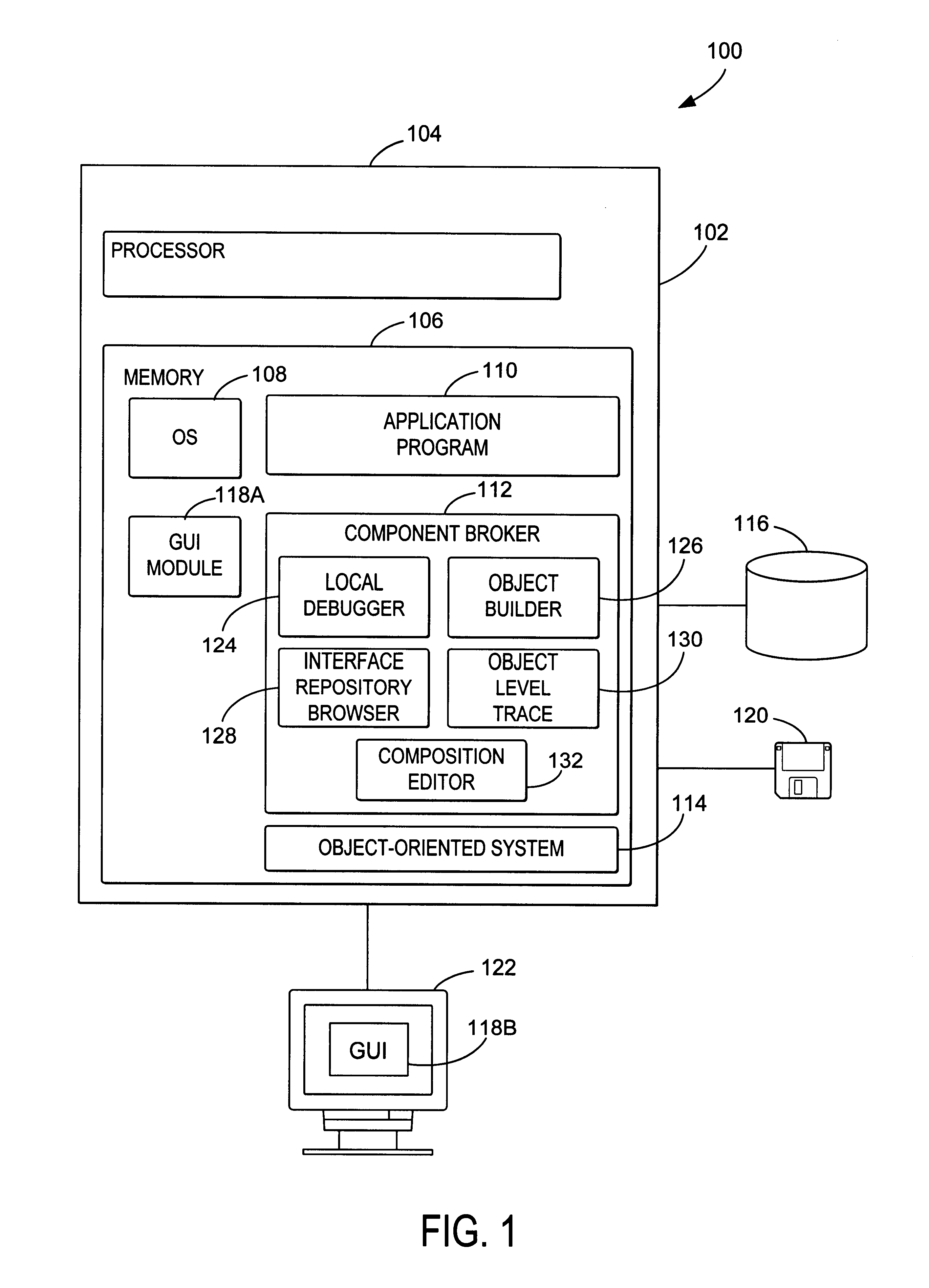
FIG. 1 illustrates an exemplary computer system 100 that could be used to implement the present invention. The computer 102 comprises a processor 104 and a memory (RAM) 106. The computer 102 is operatively coupled to a display 122, which presents images such as windows to the user on a graphical user interface 118B. The computer 102 may be coupled to other devices, such as a keyboard, a mouse device, a printer, etc. Of course, those skilled in the art will recognize that any combination of the above components, or any number of different components, peripherals, and other devices, may be used with the computer 102.

Generally, th...


PUM


Abstract

A system, method, and article of manufacture for intuitively defining new attributes and methods as a function of existing attributes and methods is described. The method comprises the steps of creating a composite object having object elements including methods and attributes combined according to a composition rule, displaying a view of expression elements comprising the attributes and methods of the composite object, defining an object element expression combining at least two of the expression elements, and forming the hybrid object element from the selected expression elements. In one embodiment, a drop-down list is used to select a series of attributes, methods and operators that comprise the expression defining the hybrid element. The apparatus comprises means for performing the operations above, including a computer with a processor and memory coupled to a data storage device and a display. The article of manufacture comprises a tangible embodiment of instructions for performing the foregoing operations.

Description

This application is related to the following co-pending and commonly assigned application, which application is hereby incorporated by reference herein:application Ser. No. 09 / 127,467, filed on same date herewith, now pending by Philip T. Berkland, Howard J. Glaser, David J. Kuettel, Stewart E. Nickolas, and John C. Sanchez, entitled "Method for Defining Composed Object Methods and Attributes by Dynamically Presenting Composite Values and Options".1. Field of the InventionThe present invention relates to systems and methods of object-oriented programming, and in particular to a method and system for creating new object methods and object attributes and for editing existing methods and attributes.2. Description of the Related ArtObject oriented programming has become increasingly popular among software developers, because it offers the benefits of increased application portability, interoperability, and interchangeability. Object-oriented programming techniques also reduce developmen...

Claims


Application Information

Patent Timeline
Patent Type & Authority Patents(United States)
IPC IPC(8): G06F9/44
CPCG06F8/36Y10S707/99944
Inventor BERKLAND, PHILIP THEODOREGLASER, HOWARD JUSTINNICKOLAS, STEWART EARLE
Owner IBM CORP
Why Eureka
Try Eureka