
Composite object and method for the production thereof

A technology of composite materials and oxidized materials, which is applied in the field of manufacturing composite materials, can solve the problems of not being able to implement, not expecting heat conduction, and not being able to achieve glass contact, etc.

Inactive Publication Date: 2011-05-04
瑞士材料试验研究所
View PDF4 Cites 18 Cited by
  • Summary
  • Abstract
  • Description
  • Claims
  • Application Information

AI Technical Summary

Problems solved by technology

However, it proves problematic here that the use of such a U-shaped profile requires a large number of struts over a large area, which produces a large amount of undesired heat conduction
For this reason, a tight anodic bond can hardly be achieved in this way over the entire area, since the same contact with the glass cannot be achieved over the entire area.
[0013] Anodic bonding was also considered for the manufacture of microelectromechanical systems (MEMS), but could not be implemented

Method used


Image

  • Composite object and method for the production thereof
  • Composite object and method for the production thereof
  • Composite object and method for the production thereof

Examples


Embodiment Construction

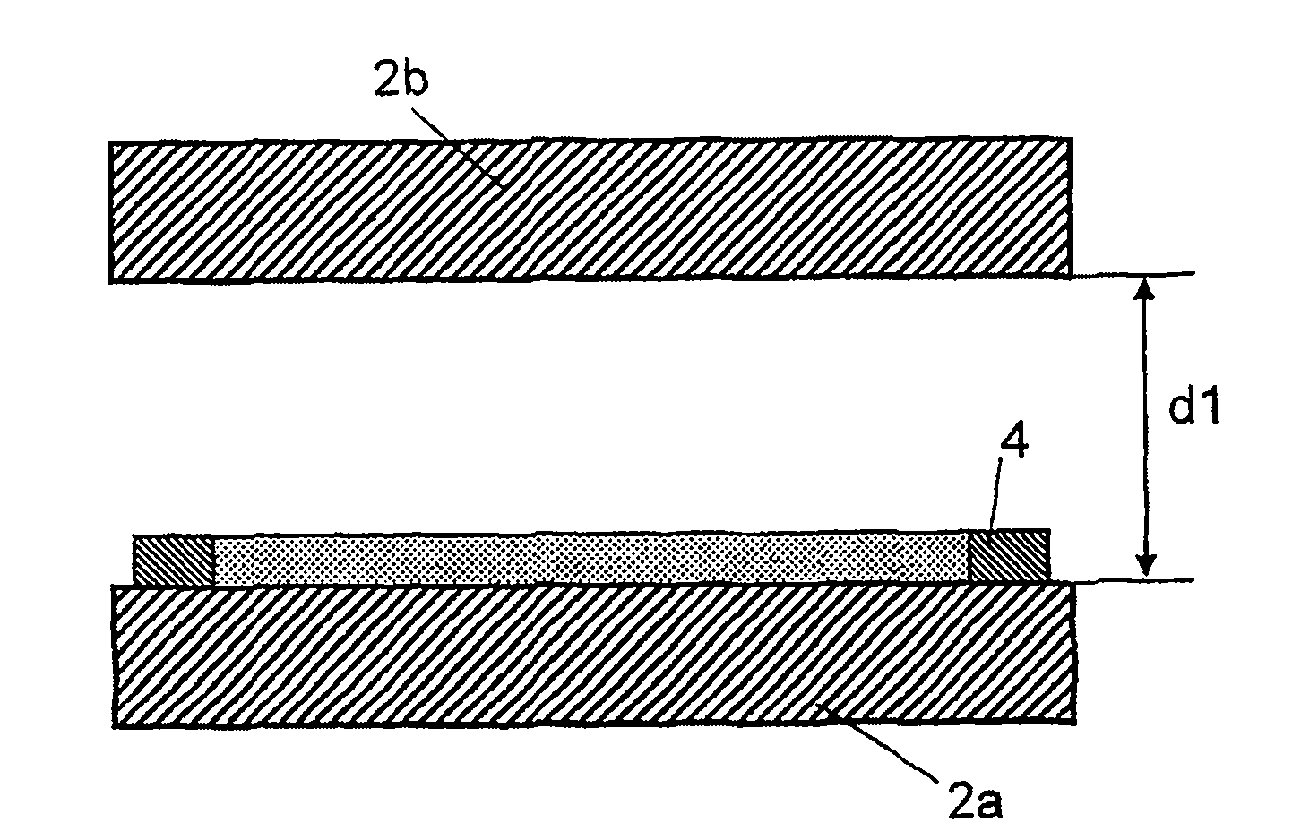
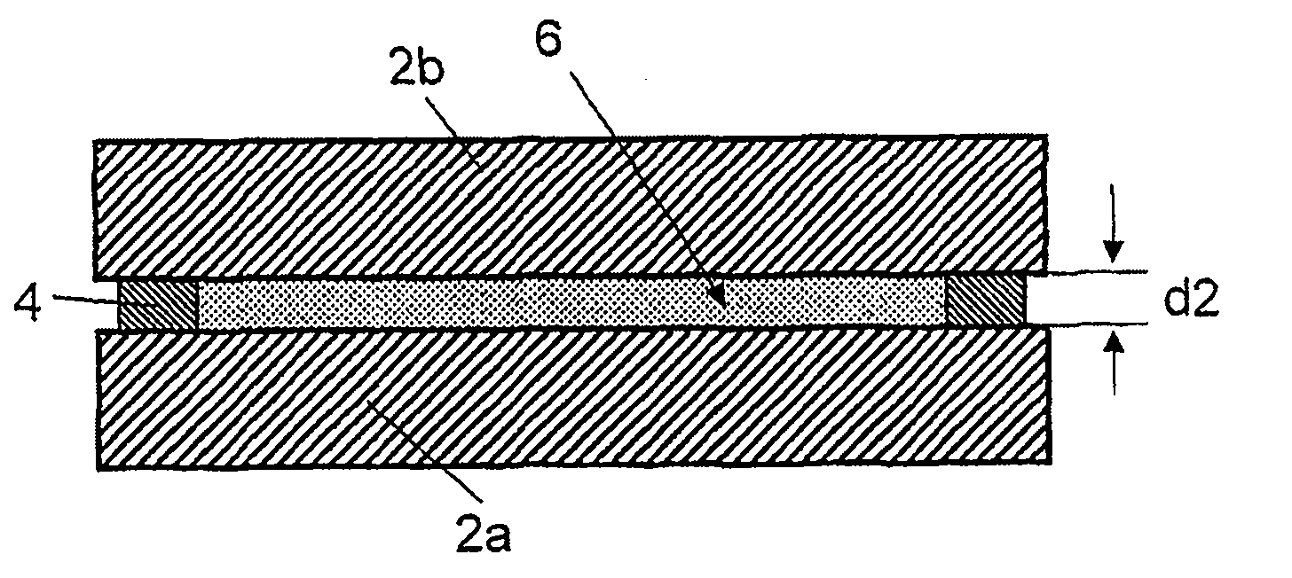
[0060] exist Figure 1a with 1b The embodiment shown in first provides two plate-shaped glass elements 2a and 2b, which have previously been subjected to a cleaning step. The two glass elements are basically aligned horizontally and are initially set at a distance d1 above and below, as in Figure 1a shown. The distance d1 is chosen such that a problem-free venting is then possible, correspondingly eg 5 cm. The lower glass element 2 a is covered with a layer 4 of a tin alloy. As will be explained in more detail below, this is a low-melting tin alloy with a melting point of up to 350° C., which contains at least one reactive metal as an alloy constituent. The geometry of the cut layer 4 corresponds to the bonding region to be bonded in a media-tight manner. For example, to form a media-tightly closed interior 6 between the two glass elements 2a and 2b, a frame-shaped layer 4 is used that surrounds the glass elements in the vicinity of their edges.

[0061] The two glass e...


PUM

PropertyMeasurementUnit
melting pointaaaaaaaaaa
thicknessaaaaaaaaaa

Abstract

A composite object comprises two components (2a, 2b) made of an oxidic material, which at an elevated temperature conducts ions, said components being connected to each other in a medium-tight manner by way of a solder bridge (4) in a connecting region (6) located in between. In order to form a reliable connection, it is proposed that the solder bridge is formed by a low-melting tin alloy that has a weight proportion of at least 65% tin and a melting point of no more than 350 C and comprises at least one activating metal as an alloying constituent.

Description

technical field [0001] The invention relates to a composite material (Verbundobjekt) having the preamble of claim 1 and to a method for producing the composite material. Background technique [0002] Composite materials of this type, for example for microelectromechanical systems (MEMS) and in the form of highly insulating laminates or packages in semiconductor technology, are known in large numbers. [0003] With regard to the first application, a great improvement in the thermal insulation capacity is achieved by a two-layer sheet of sandwich construction, the cavity of which is kept at vacuum. The same applies to multi-layer sheets. [0004] In order to produce such glass composite materials, it is known to bond components, in particular glass sheets, which are to be composited together, in a hermetically sealed manner by means of a joining process, in particular a welding process. The soldering process is usually carried out at atmospheric pressure and the resulting ca...

Claims


Application Information

Patent Timeline
Patent Type & Authority Applications(China)
IPC IPC(8): E06B3/663E06B3/673
CPCC03C27/08C04B37/006C04B2237/12C04B2237/126C04B2237/128C04B2237/708E06B3/66342E06B3/67334B23K35/262H01L31/0488Y02E10/50B81C2203/035B81C1/00269B81C2201/019B81C2203/0118Y10T428/1317Y10T428/24744
Inventor 马赛厄斯·科布尔海因里希·曼兹
Owner 瑞士材料试验研究所
Learn More