Multi-element composite object

a composite object and multi-element technology, applied in the direction of gearing, soldering apparatus, hoisting equipment, etc., can solve the problems of unsuitable powerplant and transmission applications, impression of vulnerability associated with aluminum components, and ineffective traditional welding and casting methods for joining these alloys together

Inactive Publication Date: 2001-12-04
CLAXTON RAYMOND J
View PDF2 Cites 18 Cited by
  • Summary
  • Abstract
  • Description
  • Claims
  • Application Information

AI Technical Summary

Problems solved by technology

Unfortunately, traditional welding and casting methods are practically ineffective for joining these alloys together.
Despite the fact that aluminum is used extensively in the aircraft industry, there is an impression of vulnerability associated with some aluminum components.
This impression is that, while aluminum is a very desirable material for airframes, it is unsuitable for powerplant and transmission applications.
Aluminum components introduce a temperature limitation of approximately 350.degree. F., above which the metal begins to thermally soften.

Method used


Image

  • Multi-element composite object
  • Multi-element composite object
  • Multi-element composite object

Examples


Embodiment Construction

While the invention is susceptible of embodiment in many different forms, there are shown in the drawings, and will herein be described in detail, exemplary embodiments, with the understanding that the present disclosure is to be considered as illustrative of the principles of the invention and not intended to limit the invention to the exemplary embodiments shown and described.

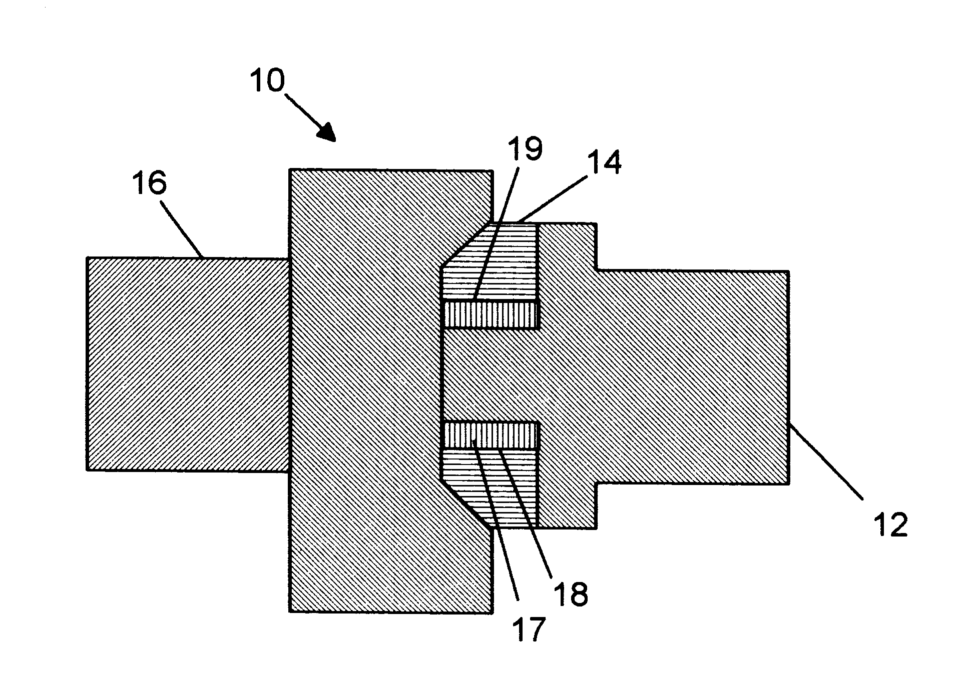
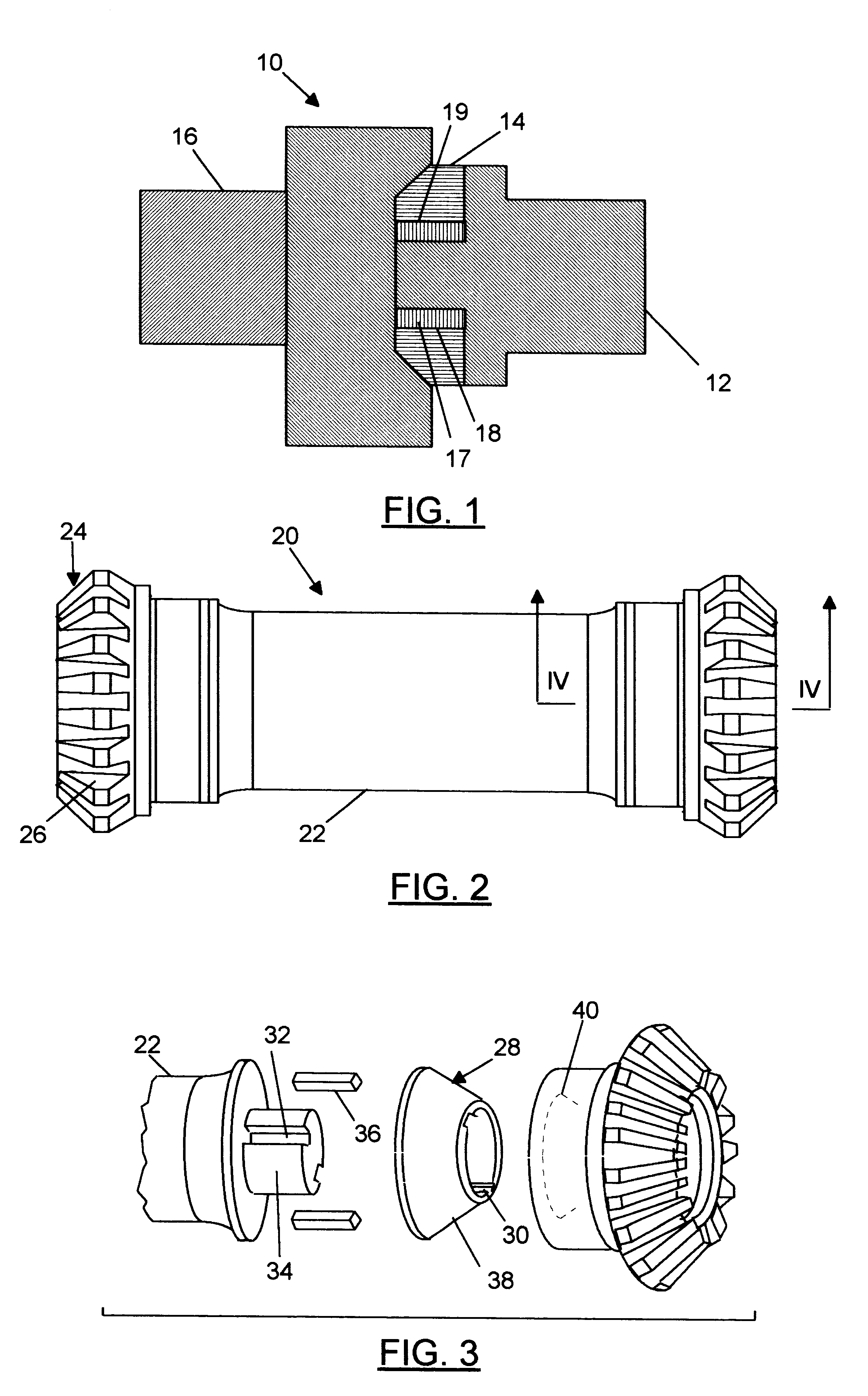
A multi-metal composite object 10 is shown in FIG. 1. The multi-metal composite object 10 is illustrated as what is commonly known as a torsion test coupon. The multi-metal metal composite object 10 includes a first component 12, a second component 14, and a third component 16. The first component 12 is fabricated from a first metal selected to provide a desired characteristic, for example, the component 12 may be fabricated from a titanium alloy, such as Ti-6Al-4V, to provide reduced weight. The third component 16 is fabricated from a second metal selected to provide a different desired characteristic, for e...


PUM

PropertyMeasurementUnit
temperatureaaaaaaaaaa
temperaturesaaaaaaaaaa
temperatureaaaaaaaaaa

Abstract

A multi-element composite object composed from first, second, and third metal components is provided, wherein the first metal and the third metal are weld incompatible. The multi-element composite object includes a first component fabricated from a first metal. A second component, fabricated from a second metal, is brazed to the first component A third component, fabricated from a third metal, is inertia welded to the second component . The first metal may be provided as a titanium alloy, e.g. a TiNi alloy. The second metal may be provided as low-carbon mild or alloy steel. The third metal may be provided as alloy steel, e.g., 9310 nickel alloy steel. In an embodiment, the multi-element composite object is a gear assembly, with the first element of the gear assembly object being a shaft and the third element of the gear assembly being a gear member with hardened teeth surfaces. The first and second components can be mechanically keyed together via an anti-rotational element. The anti-rotational element can be provided as a pin-in-groove arrangement or a twist-fit arrangement A method of making a multi-metal composite object including a first component fabricated from a first metal, a second component fabricated from a second metal, and a third component fabricated from a third metal, wherein the first metal and the third metal are weld incompatible, is also disclosed. The first step of the method includes mechanically keying the first component to the second component. Net, the first component is brazed to the second component. Finally, the third component is welded to the second component. Where the first metal is a Ti alloy and the second metal is low-carbon steel, the step of brazing the first component to the second component can include brazing using a brazing material such as Ag and Cu. Where the third component is heat-treated steel, the assembly can be stress-relieved after inertia welding at a temperature sufficiently low so as not to degrade the heat-treated properties of the third component.

Description

STATEMENT AS TO RIGHTS TO INVENTIONS MADE UNDER FEDERALLY-SPONSORED RESEARCH AND DEVELOPMENTNone.None.The invention relates generally to multi-element composite objects. In particular, the invention relates to multi-element composite objects fabricated from weld-incompatible metals.DESCRIPTION OF RELATED ARTObjects employing combinations of different metals, so-called "composite objects" are hardly new. For example, archaeologists have discovered artifacts combining iron and bronze components that date from before the birth of Christ. One basic premise present in these primitive metallurgical developments has carried through the centuries: the desirable characteristics of different metals may be combined by their use in a single object.One modern application of this premise is in the aircraft industry. It is well-recognized that every gram of weight that can be removed from an aircraft will pay large dividends by way of reduced fuel consumption, increased performance, or increased p...

Claims


Application Information

Patent Timeline
Patent Type & Authority Patents(United States)
IPC IPC(8): B23K1/00B23K1/19B23K20/12B23K35/00C22C14/00F16H55/06
CPCB23K1/0008B23K20/129B23K35/005C22C14/00B23K1/19Y10T428/12896B23K35/004F16H55/06Y10T428/12965Y10T428/12493Y10T428/12806Y10T74/19688Y10T74/19693Y10T428/12979Y10T428/12924
Inventor CLAXTON, RAYMOND J.
Owner CLAXTON RAYMOND J
Why Eureka
Try Eureka