Connector with upper and lower inner housing members

a technology of inner housing and connection rod, which is applied in the direction of coupling device connection, two-part coupling device, contact member penetrating/cutting insulation/cable strand, etc., can solve the problems of unintentional separation of locking member 105 and cavity alteration

Inactive Publication Date: 2001-05-15
SUMITOMO WIRING SYST LTD
View PDF6 Cites 37 Cited by
  • Summary
  • Abstract
  • Description
  • Claims
  • Application Information

AI Technical Summary

Problems solved by technology

In such a case, the inner members 102 may shift position; problems may occur, such as t...

Method used


Image

  • Connector with upper and lower inner housing members
  • Connector with upper and lower inner housing members
  • Connector with upper and lower inner housing members

Examples


Embodiment Construction

An embodiment of the present invention will be explained with the aid of FIGS. 1 to 21.

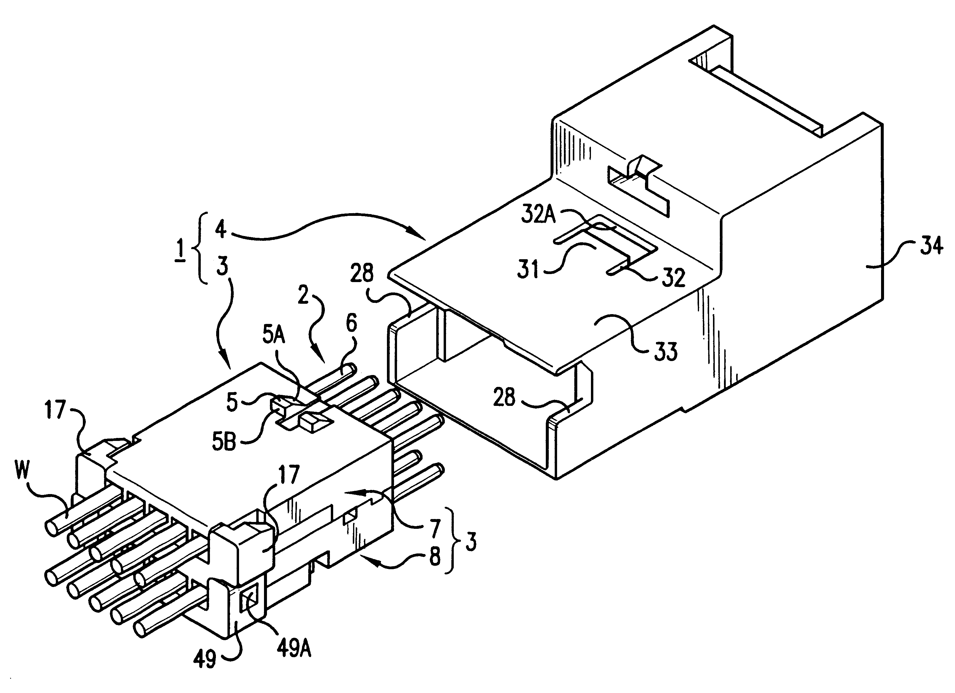
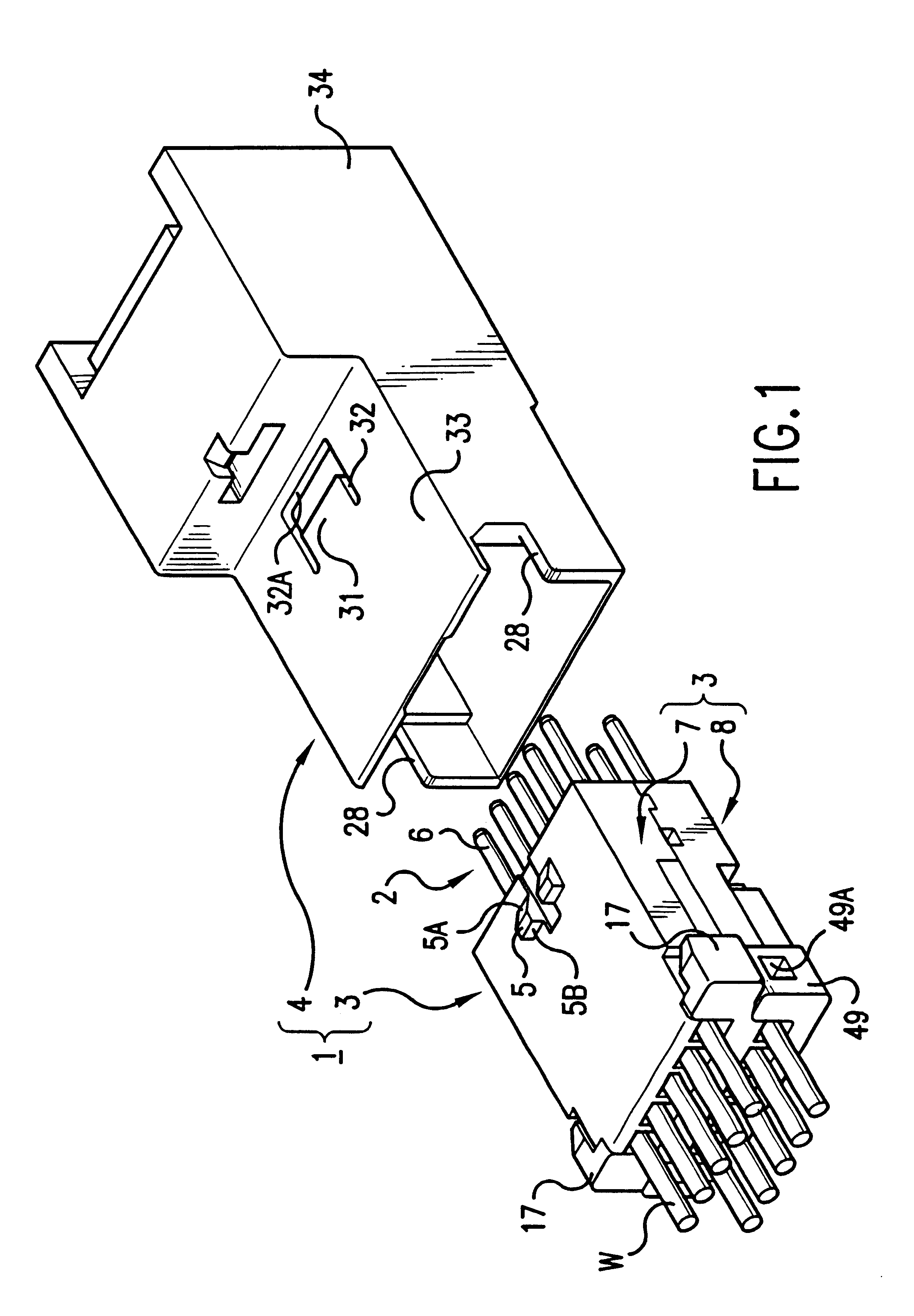
As FIG. 1 shows, a connector 1 comprises an inner member 3 for housing terminal fittings 2, and an outer member 4 which houses the inner member 3. As will be explained later, the inner member 3 comprises connected upper and lower inner members 7 and 8. In order to simplify the explanation, inner member 3 will refer to both the upper and lower inner members 7 and 8 when these are in a joined-together state.

In the following explanation, as shown in FIG. 1, the direction in which stopping protrusions 5 of the inner member 3 protrude will be considered to be the upper side, while the direction in which tabs 6 of the terminal fittings 2 protrude from the inner member 3 will be considered to be the anterior side.

Terminal Fittings

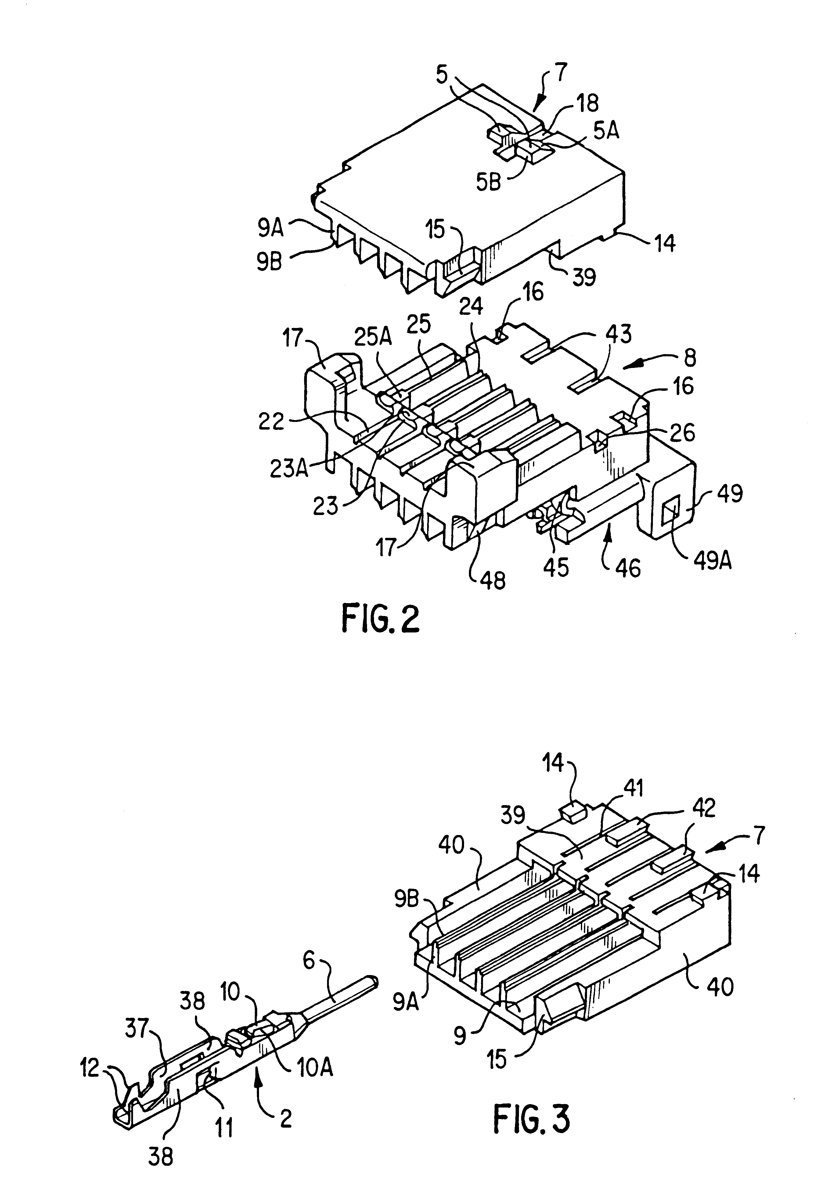
As shown in FIG. 3 etc., the terminal fittings 2 are provided on the male side and comprise electrically conductive sheet metal which has been bent, these joining with correspon...


PUM


Abstract

A connector including an inner housing member for housing terminal fittings and an outer member for receiving the inner housing member. The inner housing member comprises upper and lower inner members. After terminal fittings have been attached to the upper and lower inner members, these inner members are joined to one another to form the inner housing member. An angular-tubular shaped housing chamber is provided at the posterior of an outer member for housing the inner housing member. The inner housing member is pushed into the housing chamber of the outer member to complete the assembly of the connector. The connector also includes a latch that prevents the inner and outer members from being easily released, and in which rattling or vibration of the upper and lower inner members is prevented.

Description

The present invention relates to an electrical connector.BACKGROUND TO THE INVENTIONFIG. 22 of this specification shows a connector as described in JP-2-148583. This connector comprises an outer member 101 which allows the insertion of pressure contact terminal fittings (not shown) at three levels in a height-wise direction. This outer member 101 has spaces formed in a unified manner which allow the insertion of the pressure contact terminal fittings in the upper step, while the middle and lower steps accommodate two separate inner members 102, each formed as separate bodies, and both being capable of being inserted into the outer member 101. An angular tubular shaped attachment region 104 is provided on the anterior portion of the outer member 101, the portion thereof which houses the terminal fittings of the upper step forming terminal housing chambers 103. These terminal housing chambers 103 are partitioned, from left to right, into four compartments, and open out in an upwards d...

Claims


Application Information

Patent Timeline
IPC IPC(8): H01R13/506H01R13/502H01R13/514H01R4/24H01R13/639H01R24/00
CPCH01R13/506H01R13/514
Inventor FURUTANI, MITSUGUAOYAMA, MASAHIKO
Owner SUMITOMO WIRING SYST LTD
Why Eureka
Try Eureka