Method for replacing parts of a digitally coded picture, and device for carrying out the method

a technology of digitally coded pictures and parts, applied in image data processing, color television, television systems, etc., to achieve the effect of preventing memory access conflicts and incorrect displays

Inactive Publication Date: 2001-05-15
DEUTSCHE THOMSON-BRANDT GMBH
View PDF5 Cites 2 Cited by
  • Summary
  • Abstract
  • Description
  • Claims
  • Application Information

AI Technical Summary

Benefits of technology

The object of the invention, therefore, is to specify a method for replacing parts of a digitally coded picture which enables specific replacements to be made even in the compressed pixel data of the previously described sub-pictures, with the result that the majority of the pixel data can remain unchanged and it is not necessary to provide a completely new sub-picture unit in the memory.
The method according to the invention has the advantage over the method known from the prior art that sub-picture units having compressed pixel data can be altered at least in parts, with the result that changes to the sub-picture can be effected without the necessity of providing a completely new sub-picture unit in a memory e.g. of a film playback device. Furthermore, it becomes possible for additional pixel data easily to be attached to the replaceable part of the sub-picture, or be inserted, without completely new coding of the pixels of the picture being necessary.
Today's customary television standards such as NTSC and PAL employ the known line interlacing method. In this case, each picture is divided into two fields that are interleaved in one another. This is also taken into account in the production of sub-picture units according to the DVD standard. A sub-picture is likewise divided into two fields. The pixel data (PXD) of the lines of each field are stored in separate memory areas. In this case, it is very advantageous for the method for replacing parts of the digitally coded picture if the field which is currently being decoded and displayed is signalled and a replacement of parts of the lines of the picture is allowed only in that field which is currently not being decoded and displayed. Memory access conflicts and incorrect displays are thereby prevented from the outset.

Problems solved by technology

This gives rise to the problem that if frequent changing of the sub-pictures is necessary for certain applications, all of the possible sub-pictures have to be stored individually in the memory, even if they differ only slightly from one another.

Method used


Image

  • Method for replacing parts of a digitally coded picture, and device for carrying out the method
  • Method for replacing parts of a digitally coded picture, and device for carrying out the method
  • Method for replacing parts of a digitally coded picture, and device for carrying out the method

Examples


Embodiment Construction

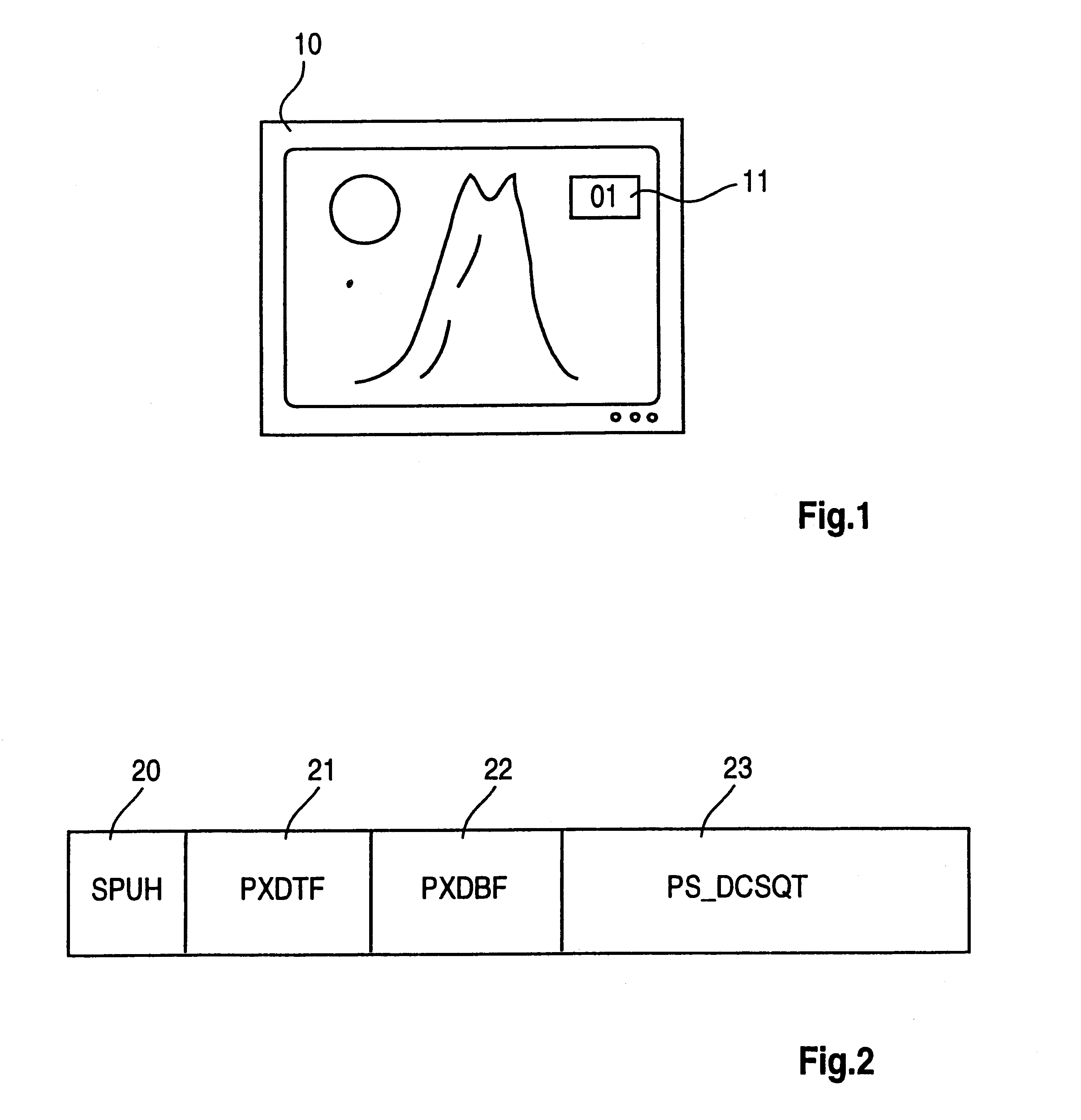
The invention is described using the example of a television receiver having a sub-picture decoding device for displaying or inserting sub-pictures on the screen of the television receiver. Such a television receiver is illustrated in FIG. 1 and designated by the reference symbol 10. A main picture showing a mountain landscape is displayed on the screen of the television receiver. A sub-picture, which is provided with the reference symbol 11, is additionally displayed in the top right corner on the screen of the television receiver. This sub-picture 11 serves to display the current programme location number. The first programme location is illustrated. In the event of a switch-over to a different channel, the associated programme location would be displayed as sub-picture 11.

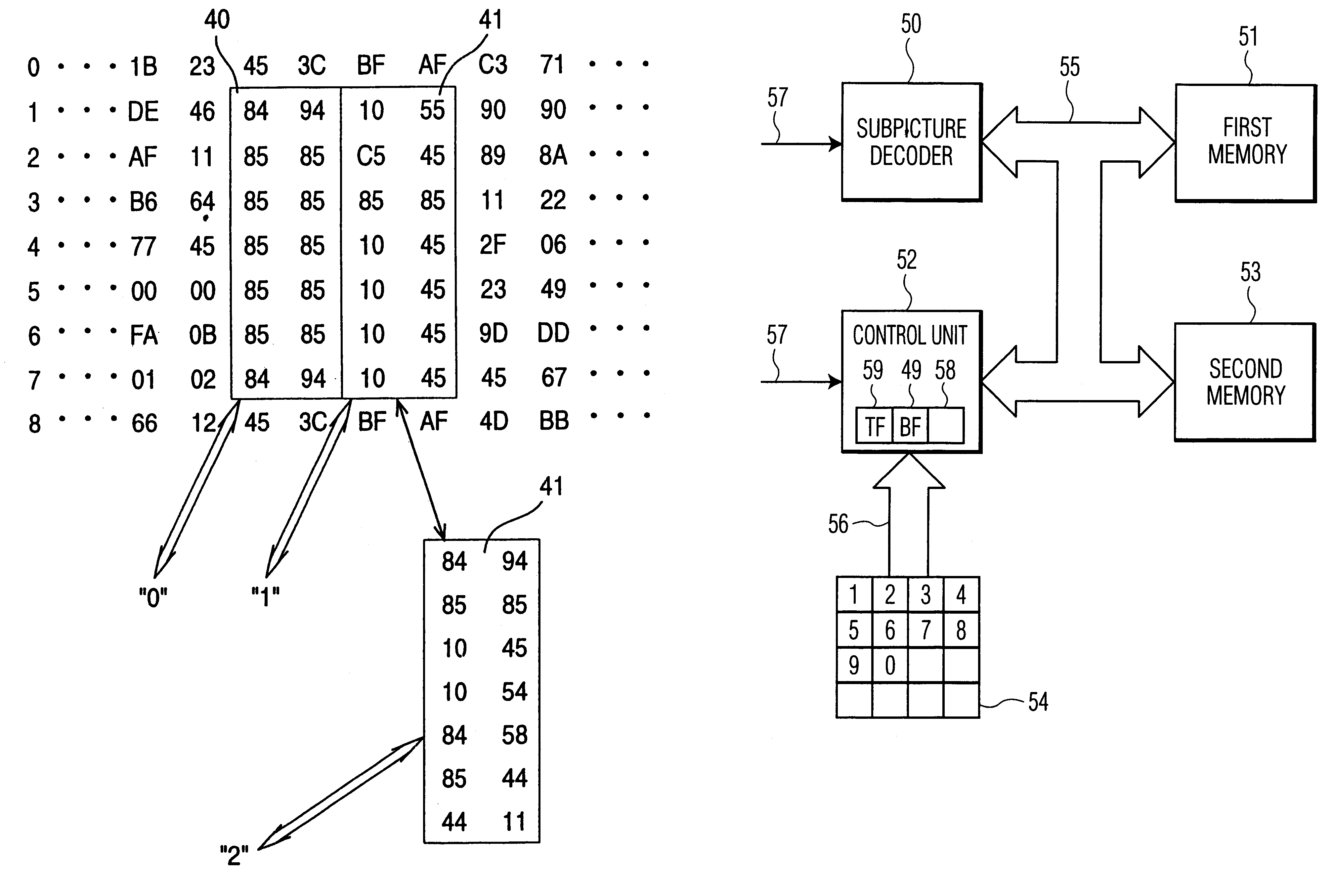
The sub-picture 11 is displayed with the aid of a sub-picture decoding device, which is explained in more detail below. This sub-picture decoding device largely corresponds to a sub-picture decoding device as di...


PUM


Abstract

A method for replacing parts of a digitally coded picture (11) is proposed. The digitally coded picture (11) may correspond to a sub-picture which is displayed on the screen of a television set (10). In the method, each line of the picture (11) is run length-coded. The replaceable parts of a line of the picture are run length-coded separately. The part which replaces the replaceable, original part of a line of the picture (11) is run length-coded in such a way that it has the same number of data units (data bytes) as the original part of this line of the picture (11). The replacement of the data for the run length coding words is carried out in a memory device (51). The replacement is possible in a simple manner by virtue of the fact that the original part of a line of the picture and the new part of the line of the picture have the same number of data units. Moreover, a device for carrying out the method is also proposed.

Description

The invention relates to a method for replacing parts of a digitally coded picture and to a device for carrying out the method for replacing parts of a digitally coded picture, in particular a video picture.PRIOR ARTThe invention is based on a method for replacing parts of a digitally coded picture. In video technology, it is known to provide so-called sub-picture decoding devices in film playback devices, for example a DVD playback device, for displaying e.g. subtitles on the screen of a television set. DVD playback devices of this type are currently commercially available and contain the abovementioned sub-picture decoding devices. The DVD standard (Version 1.0) provides a number of explanations concerning such sub-picture decoding devices, which are designated as sub-picture decoders therein. All of the sub-pictures to be displayed are stored in a special format. In this case, the data of the individual pixels are stored in compressed form in a so-called sub-picture unit (SPU).IN...

Claims


Application Information

Patent Timeline
Patent Type & Authority Patents(United States)
IPC IPC(8): G06T9/00H04N7/58H04N7/52H04N5/45H04N5/92H03M7/46H04N7/26
CPCG06T9/005H04N5/45H04N21/2365H04N21/4347H04N21/4316
Inventor WINTER, MARCO
Owner DEUTSCHE THOMSON-BRANDT GMBH
Why Eureka
Try Eureka