Simple rich-lean separation device arranged in W-flame boiler

A technology of thick-thin separation and thick-thin separator, which is applied in the field of thick-thin separation devices, can solve the problems of many parts, large space occupation, complex structure, etc., and achieve the effect of fewer parts, saving space and prolonging the stroke in the furnace

Active Publication Date: 2012-07-11
HARBIN INST OF TECH
View PDF1 Cites 0 Cited by
  • Summary
  • Abstract
  • Description
  • Claims
  • Application Information

AI Technical Summary

Problems solved by technology

[0005] The object of the present invention is to provide a thick-lean separation device arranged in a W flame boiler to solve the problems of the existing W flame boiler thick-lean separation device with many parts, complex structure and large space occupation

Method used


Image

  • Simple rich-lean separation device arranged in W-flame boiler
  • Simple rich-lean separation device arranged in W-flame boiler
  • Simple rich-lean separation device arranged in W-flame boiler

Examples


specific Embodiment approach 1

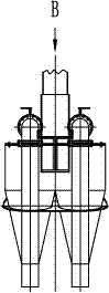
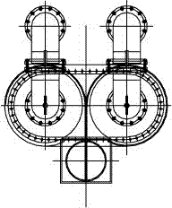
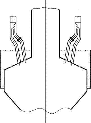
[0009] Specific implementation mode one: combine Figure 6-Figure 8 Describe this embodiment mode, a thick-lean separation device arranged in a W flame boiler in this embodiment includes a primary air pipe 2, a pulverized coal thick-lean separator 3, an exhaust gas pipeline 7, an exhaust gas baffle plate 12, and a concentrated coal dust main pipeline 4. Coal powder equalizer 14 and two concentrated coal powder pipelines 5, the lower end of the primary air pipeline 2 communicates with the upper end of the coal powder concentration separator 3, and the exhaust gas baffle 12 is installed on the exhaust gas pipeline 7, so that The thick-thin separation device also includes a thick-thin separation plate 13, and the thick-thin separation plate 13 is fixedly installed on the inner wall of the pulverized coal thick-lean separator 3, and the upper end of the exhaust gas pipeline 7 and the upper end of the thick pulverized coal main pipeline 4 are connected with the coal The lower end o...

specific Embodiment approach 2

[0010] Specific implementation mode two: combination Figure 6 and Figure 8 To describe this embodiment, the shade separation plate 13 of this embodiment is a triangular blunt body or a semicircular blunt body. Such setting reduces the abrasion of the pulverized coal on the thick-thin separation plate 13 . Other components and connections are the same as those in the first embodiment.

[0011] Working principle: The pulverized coal airflow enters the pulverized coal concentration separator 3 from the primary air duct 2, and the pulverized coal particles collide with the concentration separation plate 13. Due to the large inertia of the pulverized coal particles, the pulverized coal is concentrated to the concentration separation plate after the collision On the inner wall of the pulverized coal concentration separator 3 opposite to 13, the air inertia is very small, and the concentration separation plate 13 has little influence on the velocity direction of the air, and the ...


PUM


Abstract

The invention discloses a rich-lean separation device arranged in a W-flame boiler, relates to the rich-lean separation device arranged in the W-flame boiler and solves the problems that the conventional rich-lean separation device for the W-flame boiler has a plurality of components and a complex structure and occupies a large space. In the simple rich-lean separation device, a rich-lean separation plate (13) is fixedly arranged on the inner wall of a pulverized coal rich-lean separator (3); the upper end of an exhaust gas pipeline (7) and the upper end of a master dense pulverized coal pipeline (4) are both communicated with the lower end of the pulverized coal rich-lean separator (3); the exhaust gas pipeline (7) is positioned under the rich-lean separation plate (13); the master dense pulverized coal pipeline (4) is communicated with a pulverized coal equal divider (14); the lower end of the pulverized coal equal divider (14) is provided with dense pulverized coal pipelines(5); and the pulverized coal equal divider (14) is communicated with two dense pulverized coal pipelines (5). The device has a simple structure, saves the space, improves the reliability and spatial adaptability of a system and is applied in the technical field of burning of the W-type flame boiler.

Description

technical field [0001] The invention relates to a thick-thin separation device arranged in a W-flame boiler, in particular to a thick-thin separation device arranged in a W-flame boiler, belonging to the technical field of W-flame boiler combustion. Background technique [0002] W-type flame boiler is a boiler specially designed for burning low volatile anthracite and lean coal. In order to make the pulverized coal ignite in time, burn stably and reduce the NO in the furnace flue gas x Content, W flame boiler often adopts pulverized coal concentration separation technology. Most W flame boilers use a cyclone thick-lean separator to separate the thick-lean airflow of the pulverized coal. Although the cyclone thick-lean separator has high separation efficiency, it has large resistance. During high-load operation, the nozzle of the cyclone thick-lean separator is seriously worn. For example: the W-shaped flame boiler manufactured by FW Company in the United States has the a...

Claims


Application Information

Patent Timeline
Patent Type & Authority Patents(China)
IPC IPC(8): B07B7/04
Inventor 陈智超李争起曾令艳朱群益邢超胡志勇徐振兴
Owner HARBIN INST OF TECH
Why Eureka
Try Eureka