
Pulverized coal concentrator, pulverized coal burner and pulverized coal boiler

A pulverized coal burner and concentrator technology, which is applied in the direction of burners, burners burning powder fuel, burning with multiple fuels, etc. It can solve the problems of increasing burner resistance, failing to achieve the concentration effect, and easy wear of the blade grid. problems, to achieve the effect of improving the separation effect of thick and thin, reducing the situation of mixing in advance, and enhancing the effect of concentration

Inactive Publication Date: 2012-05-16
YANTAI LONGYUAN POWER TECH
View PDF9 Cites 2 Cited by
  • Summary
  • Abstract
  • Description
  • Claims
  • Application Information

AI Technical Summary

Problems solved by technology

[0005] In short, the performance of the pulverized coal concentrator will directly affect the concentration separation effect of the pulverized coal airflow, and then affect the overall performance of the pulverized coal burner
[0006] The above-mentioned louver pulverized coal concentrator is provided with multiple cascades on the pulverized coal airflow channel, which uses the impact of the airflow and the inertial difference between the gas and solid phases to generate density separation; At a certain angle, there will be two adverse effects: one is that the resistance of the burner is greatly increased; the other is that the cascade is easily worn by the impact of coal powder
As for the elbow concentrator, although the density separation caused by the inertia difference between the gas and solid phases when the pulverized coal flow passes through the elbow is used, the resistance added by the burner is less while concentrating the pulverized coal; No follow-up mandatory isolation measures are taken. After a certain distance, the dense phase of pulverized coal airflow and the light phase of pulverized coal airflow will be mixed, so that the concentration of pulverized coal will be restored quickly; therefore, it cannot be achieved in practical applications To the ideal concentration effect, and then affect the overall performance of the pulverized coal burner

Method used


Image

  • Pulverized coal concentrator, pulverized coal burner and pulverized coal boiler
  • Pulverized coal concentrator, pulverized coal burner and pulverized coal boiler
  • Pulverized coal concentrator, pulverized coal burner and pulverized coal boiler

Examples


Embodiment 1

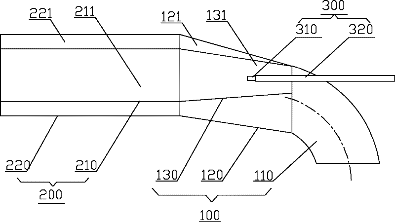
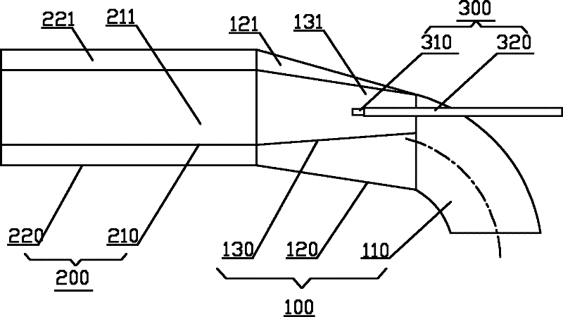
[0030] Please refer to figure 1 , which is a schematic structural view of a pulverized coal burner provided in Embodiment 1 of the present invention. The pulverized coal burner includes a double-layer cylinder 200 , a pulverized coal concentration section 100 , an ignition device 300 and other parts. The pulverized-coal concentration section 100 can separate the pulverized-coal airflow of the primary air from thick to thin to form a pulverized-phase dense-phase airflow and a pulverized-coal light-phase airflow. Used to ignite dense-phase pulverized coal gas stream.

[0031] The double-layer cylinder 200 includes a main body section 220 and a partition 210 located in the main body section 220; the partition board 210 extends along the coal powder flow direction, and divides the inside of the main body section 220 into a dense phase pulverized coal channel 211 and a light phase pulverized coal channel 221. In this example, the main body section 220 and the partition plate 210 ...

Embodiment 2

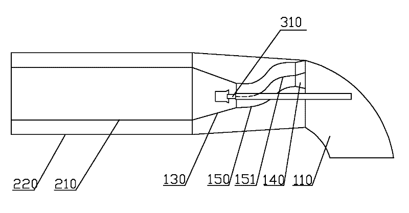
[0038] Please refer to figure 2 , which is a schematic structural diagram of the pulverized coal burner provided in Embodiment 2 of the present invention. Compared with embodiment one, in embodiment two, the pulverized coal concentrator in the pulverized coal concentrating section also comprises the shrinkage cavity section 140 of the flow cross section of the front end greater than the flow section of the rear end, and the shrinkage cavity section 140 rear end and as inner The front ends of the tapered barrel section 130 of the barrel are connected, and the front end is opposite to the part of the rear end of the elbow 110 which is biased toward the outer arc. Since the flow section at the front end of the shrinkage cavity section 140 is larger than the flow section at the rear end, the shrinkage cavity section 140 can produce an equal flow effect on the dense-phase pulverized-coal airflow, so that the pulverized coal in the dense-phase pulverized-coal airflow is distributed...


PUM


Abstract

The invention discloses a pulverized coal concentrator, a pulverized coal burner comprising the pulverized coal concentrator and a pulverized coal boiler comprising the pulverized coal burner. The disclosed pulverized coal concentrator comprises an elbow, an outer cylinder and an inner cylinder arranged in the outer cylinder, the front end of the outer cylinder is connected with the back end of the elbow, and the back end of the outer cylinder stretches out backwards, the inner cylinder comprises a conical cylinder segment, the through-flow section of a front end of the conical cylinder segment is smaller than that of a rear end of the conical cylinder segment, the rear end of the conical cylinder segment stretches out backwards, the front end of the conical cylinder segment is communicated with the part at the back end of the elbow, which is deflected to an outer arc. The pulverized coal concentrator in the invention can separate concentrated phase pulverized coal airflow and light phase pulverized coal airflow by utilizing the inner cylinder, the situation of mixing the concentrated phase pulverized coal airflow and the light phase pulverized coal airflow in advance is reduced, and the separating effect of the concentrated phase pulverized coal airflow and the light phase pulverized coal airflow of the pulverized coal concentrator is increased, the disclosed pulverized coal burner and the disclosed pulverized coal boiler has the corresponding technical effect.

Description

technical field [0001] The invention relates to a pulverized coal combustion technology, in particular to a pulverized coal concentrator, and also to a pulverized coal burner including the pulverized coal concentrator and a pulverized coal boiler including the pulverized coal burner. Background technique [0002] In the field of pulverized coal combustion, the concentration separation technology of pulverized coal is a key technology that is widely used; through the concentration separation technology, the pulverized coal airflow can be separated into a dense phase pulverized coal airflow and a light phase pulverized coal airflow. The effects of this are: ① improve the low-load stable combustion capability of the boiler; ② enable the boiler to obtain good anti-slagging performance; ③ reduce the NOx generation of the boiler; ④ improve the ignition performance of the burner. [0003] The more typical burners using this technology include louver-type horizontal thick-lean pulve...

Claims


Application Information

Patent Timeline
Patent Type & Authority Applications(China)
IPC IPC(8): F23D1/00F23C5/08
Inventor 王雨蓬唐宏刘武成张经武张昀伊磊龚泽儒孙树翁祁宁李平秦学堂
Owner YANTAI LONGYUAN POWER TECH
Learn More