Zoom lens and optical apparatus having the same

a technology of optical apparatus and zoom lens, applied in the field of zoom lens and optical apparatus, can solve problems such as the inability to focus

Inactive Publication Date: 2001-05-22
CANON KK
View PDF11 Cites 28 Cited by
  • Summary
  • Abstract
  • Description
  • Claims
  • Application Information

AI Technical Summary

Problems solved by technology

Further, in a case where the magnification of the negative second lens unit takes a value of "-1" in a middle way of zooming, the focusing sensitivity becomes "0", so that it happens that the focusing becomes impossible.

Method used


Image

  • Zoom lens and optical apparatus having the same
  • Zoom lens and optical apparatus having the same
  • Zoom lens and optical apparatus having the same

Examples


numerical example 2

Variable Focal Length

Numerical Example 3

Variable Focal Length

numerical example 4

Variable Focal Length

Aspheric Coefficients

TABLE 1

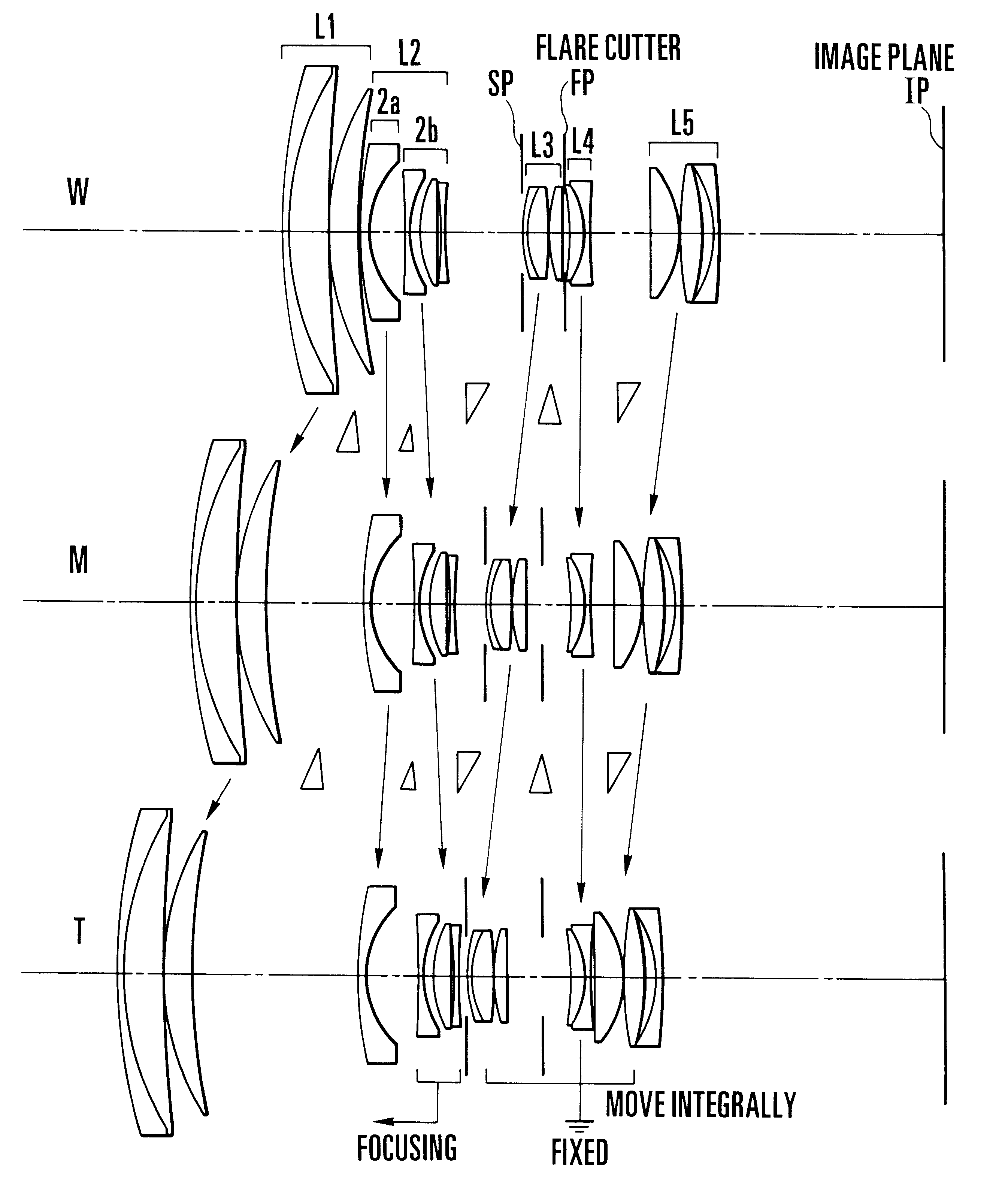
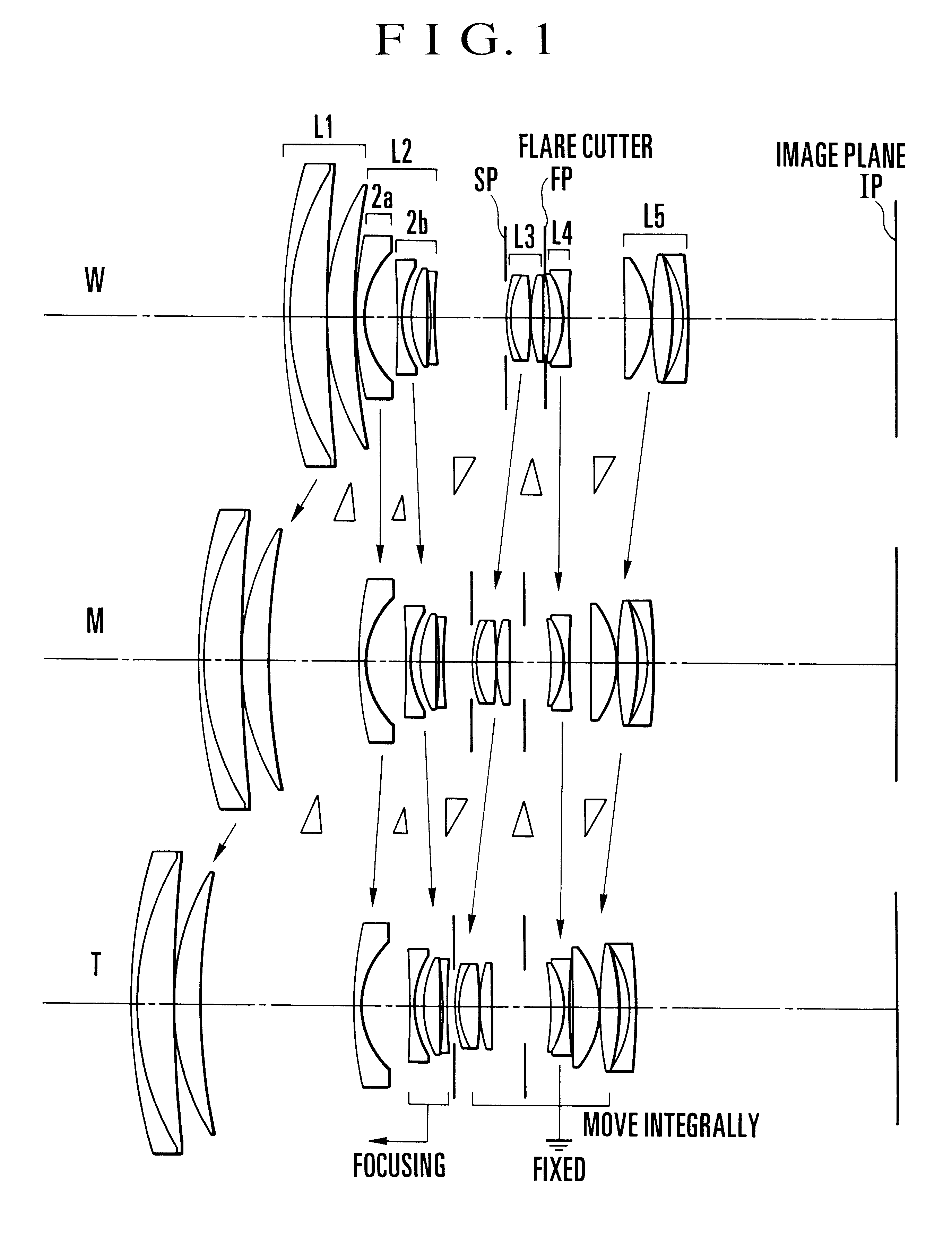
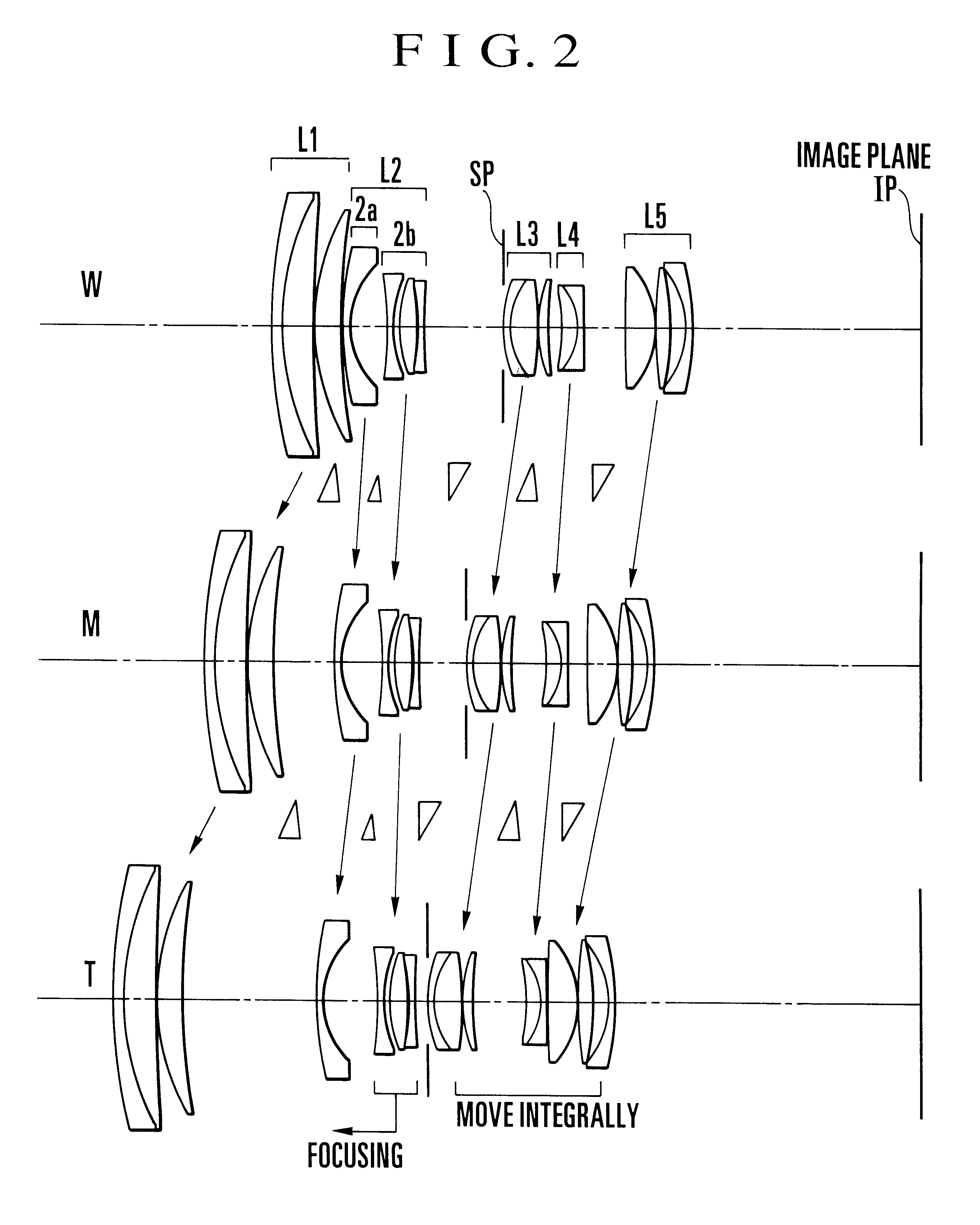
FIGS. 5Al to 5A4, 5B1 to 5B4 and 5C1 to 5C4 and FIGS. 6A1 to 6A4, 6B1 to 6B4 and 6C1 to 6C4 graphically show the aberrations of the numerical example 1 of the zoom lens of the invention. FIGS. 7A1 to 7A4, 7B1 to 7B4 and 7C1 to 7C4 and FIGS. 8A1 to 8A4, 8B1 to 8B4 and 8C1 to 8C4 graphically show the aberrations of the numerical example 2 of the zoom lens of the invention. FIGS. 9A1 to 9A4, 9B1 to 9B4 and 9C1 to 9C4 and Figs. 10A1 to 10A4, 10B1 to 10B4 and 10C1 to 10C4 graphically show the aberrations of the numerical example 3 of the zoom lens of the invention. FIGS. 11A1 to 11A4, 11B1 to 11B4 and 11C1 to 11C4 and FIGS. 12A1 to 12A4, 12B1 to 12B4 and 12C1 to 12C4 graphically show the aberrations of the numerical example 4 of the zoom lens of the invention.

In these figures, the aberration curves labeled W are in the wide-angle end, the ones labeled M in a middle focal length position and the ones labeled T at the telephoto end. FIGS. 5A...


PUM


Abstract

A zoom lens includes, in order from a longer conjugate side to a shorter conjugate side, a first lens unit of positive refractive power, a second lens unit of negative refractive power, and a succeeding lens group which is composed of a plurality of lens units or one lens unit and whose overall refractive power is positive, wherein, during zooming from a wide-angle end to a telephoto end, the separation between the first lens unit and the second lens unit increases and the separation between the second lens unit and the succeeding lens group decreases, and wherein the second lens unit includes a front lens subunit of negative refractive power and a rear lens subunit of negative refractive power disposed on the shorter conjugate side of the front lens subunit, focusing being formed by moving the rear lens subunit, and the following condition being satisfied:where fw and ft are focal lengths at the wide-angle end and the telephoto end of the zoom lens, respectively, and f2a is a focal length of the front lens subunit.

Description

1. Field of the InventionThe present invention relates to a zoom lens and an optical apparatus having the same and, more particularly, to a zoom lens of a high magnification range suited to be used in single-lens reflex cameras or video cameras.2. Description of Related ArtFor zoom lenses, there have been known a focusing method of moving the first lens unit, or the so-called "front focus" method, and another focusing method of moving the second or later lens unit, or the so-called "inner focus" or "rear focus" method.In general, the zoom lenses of the inner or rear focus type have their first lens units made smaller in diameter to admit of the effective light beam, than when the front focus type is in use. So, there is an advantage of assuring improvements of the compact form of the entire lens system. Moreover, the focusing lens unit is relatively small in size and light in weight. So, particularly for the auto-focus cameras that have recently become the main stream of development...

Claims


Application Information

Patent Timeline
Patent Type & Authority Patents(United States)
IPC IPC(8): G02B15/163G02B15/173G02B15/20
CPCG02B15/17G02B15/173G02B15/144113G02B15/145121
Inventor MISAKA, MAKOTO
Owner CANON KK
Why Eureka
Try Eureka