
Single mirror dual axis beam waveguide antenna system

a beam waveguide and single mirror technology, applied in the field of single mirror, can solve the problems of inability to rotary joints of conventional waveguides, inability to mount transmitters on the back of antennas, and complicated initial alignment of mirrors

Inactive Publication Date: 2001-06-05
RAYTHEON CO
View PDF7 Cites 7 Cited by
  • Summary
  • Abstract
  • Description
  • Claims
  • Application Information

AI Technical Summary

Problems solved by technology

Because of the large transmitters employed, it is impractical to mount the transmitter on the back of the antenna.
Moreover, due to the high power involved, conventional waveguide rotary joints are not feasible.
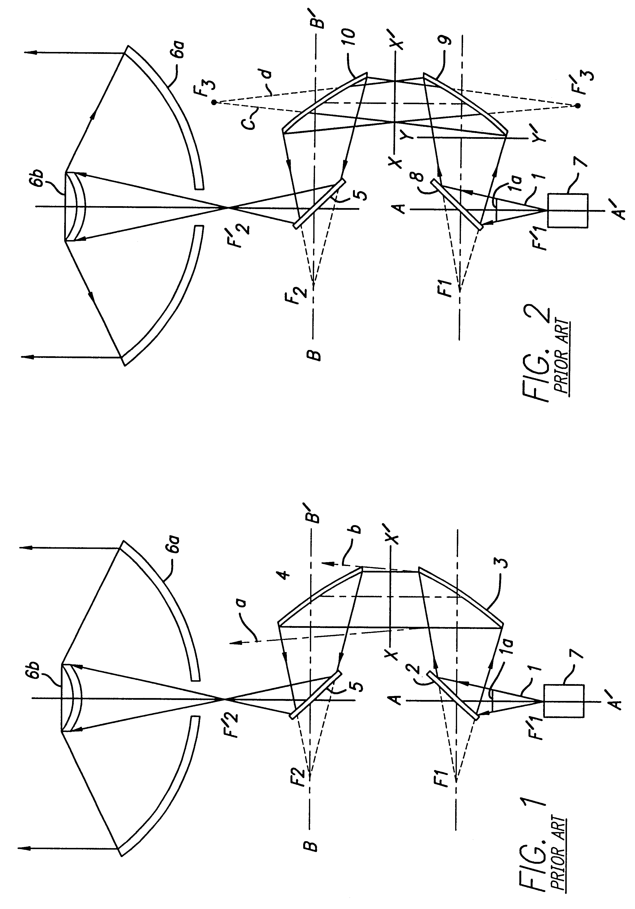
One of the drawbacks of multiple mirror arrangements, such as four-mirror beam waveguide antenna feeds, relates to alignment.
The more mirrors in a beam waveguide system, the more complicated it is to not only initially align the mirrors, but to maintain alignment over long periods of time.
However, some high power systems are required to be portable.
The designers of some portable high power systems have not used beam waveguide systems for the specific reason that the mirrors would become misaligned while the system is being transported.
Another drawback of the multiple mirror arrangements relates to power loss.
Thus, more mirrors lead to more power loss.

Method used


Image

  • Single mirror dual axis beam waveguide antenna system
  • Single mirror dual axis beam waveguide antenna system
  • Single mirror dual axis beam waveguide antenna system

Examples


Embodiment Construction

Illustrative embodiments and exemplary applications will now be described with reference to the accompanying drawings to disclose the advantageous teachings of the present invention.

While the present invention is described herein with reference to illustrative embodiments for particular applications, it should be understood that the invention is not limited thereto. Those having ordinary skill in the art and access to the teachings provided herein will recognize additional modifications, applications, and embodiments within the scope thereof and additional fields in which the present invention would be of significant utility.

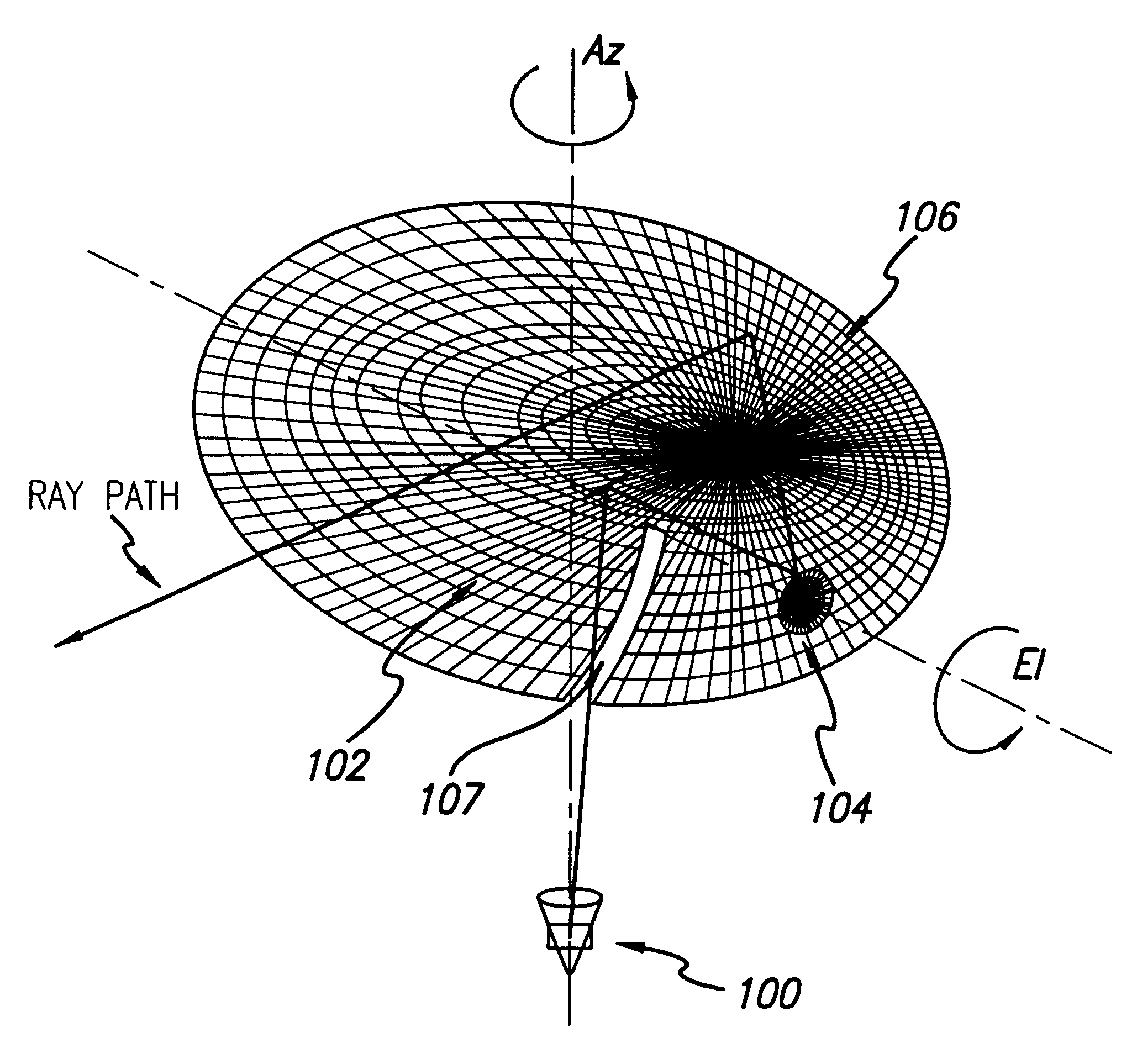
The main purpose of any beam waveguide system is to function as a rotary joint, since it often necessary to steer a reflector antenna, both in azimuth and elevation, preferably while keeping the transmitter and feed stationary. A "beam waveguide" system of mirrors allows such steering to be performed.

As previously discussed, a typical beam waveguide system is sh...


PUM


Abstract

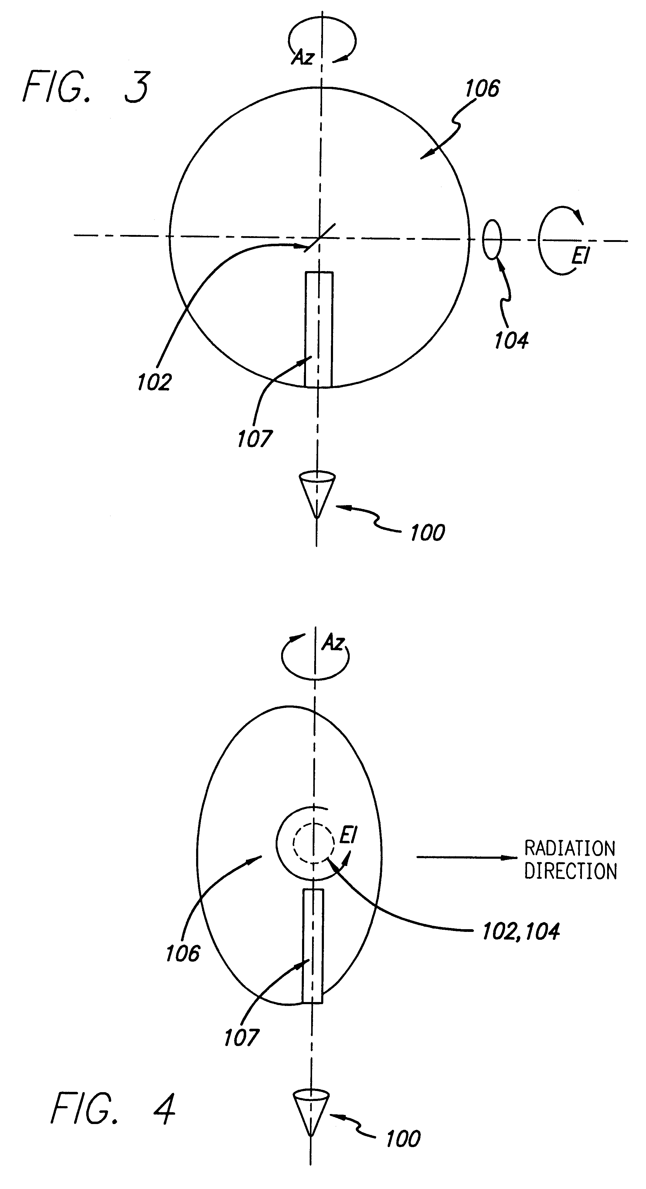
A dual axis beam waveguide antenna system includes a radiator generating a beam, a mirror which directs the beam to a subreflector, which receives the beam, and a main reflector illuminated by the subreflector, which generates a collimated output. The beam waveguide of the antenna system is characterized by an azimuth axis defined by the radiator and the mirror and an elevation axis defined by the mirror and the subreflector.

Description

1. Field of the InventionThe present invention relates to antenna systems. More specifically, the present invention relates to single mirror, dual axis beam waveguide antenna systems.2. Description of the Related ArtA large aperture antenna is used for satellite communications. Such antennas are generally of the fully steerable type, whereby a communication satellite can be tracked anywhere in the sky.Various mount systems have been developed for driving such a large aperture antenna. For example, the Jet Propulsion Laboratory employs a large aperture array in its deep space network (DSN). It will be appreciated that the DSN antennas transmit an enormous amount of power due to the extremely long communication distances, e.g., Earth to Jupiter. Because of the large transmitters employed, it is impractical to mount the transmitter on the back of the antenna. Moreover, due to the high power involved, conventional waveguide rotary joints are not feasible. Thus, four-mirror beam waveguid...

Claims


Application Information

Patent Timeline
IPC IPC(8): H01Q19/10H01Q19/19
CPCH01Q19/191H01Q19/192
Inventor BROWN, KENNETH W.
Owner RAYTHEON CO
Learn More