Connection arrangement

a technology of connecting arrangement and connection, applied in the direction of sleeve/socket joint, fluid pressure sealing joint, joint with sealing surface, etc., can solve the problem that the connection may also be prone to being inadvertently uncoupled

Inactive Publication Date: 2001-06-12
JOTT AUSTRALIA
View PDF20 Cites 14 Cited by
  • Summary
  • Abstract
  • Description
  • Claims
  • Application Information

AI Technical Summary

Benefits of technology

This form of connector can provide for the easy coupling of two objects whilst also safeguarding against the inadvertent separation of the objects when coupled together. Furthermore, one preferred form of the present invention provides for the permanent connection of the male and female components so as to prevent uncoupling of the components. An alternative preferred form of the present invention provides for the connection of the male component and female component which is lockable but which can be released to provide for the uncoupling of the components. A further preferred form of the invention provides for the connection of the male and female components such that they can be released by an axial pulling action in order to uncouple the male and female components when a pre-determined force is reached.

Problems solved by technology

However, whilst such connectors can provide for the easy coupling of the male and female components, the connectors may also be prone to being inadvertently uncoupled.

Method used


Image

  • Connection arrangement
  • Connection arrangement
  • Connection arrangement

Examples


Embodiment Construction

General

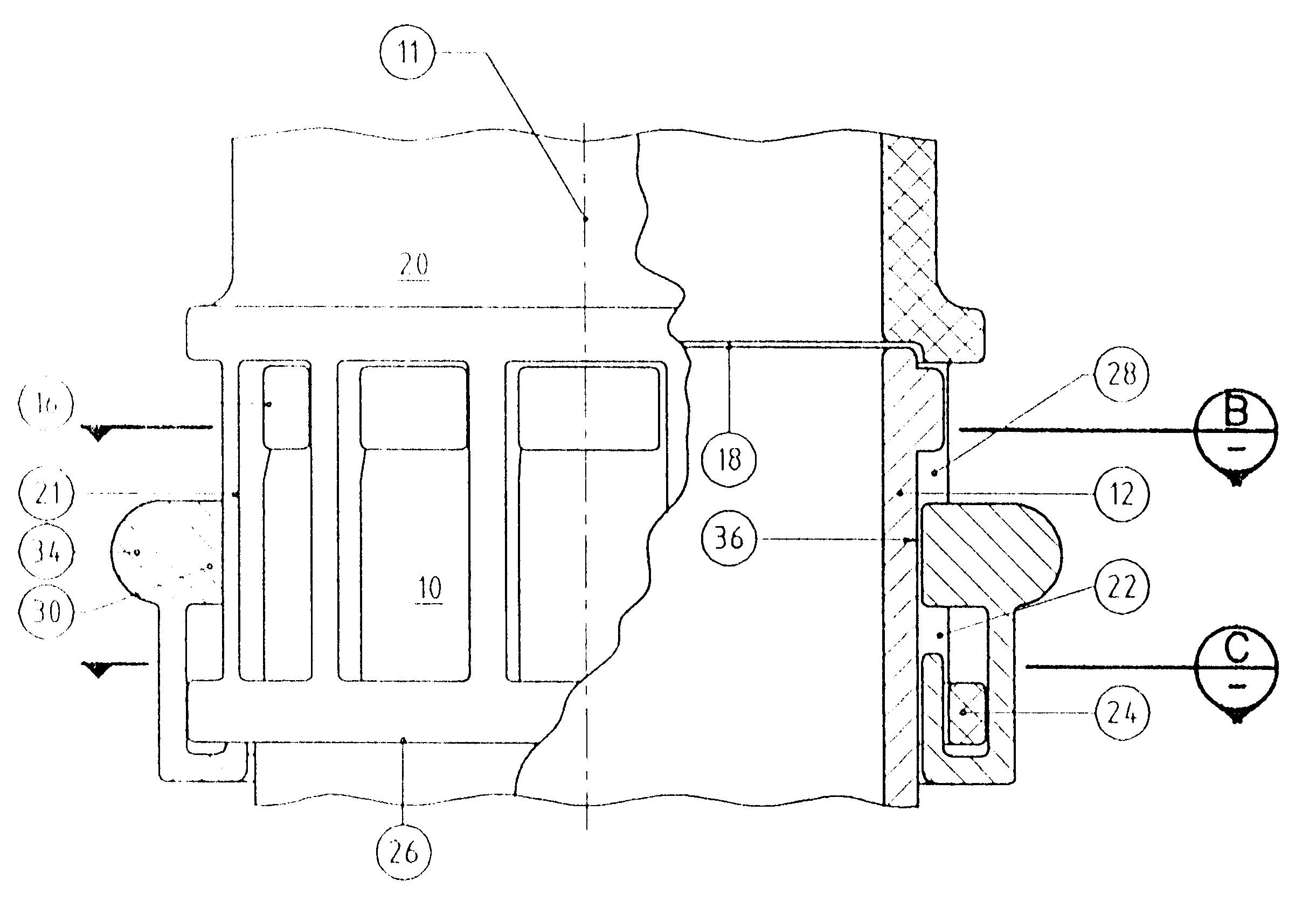
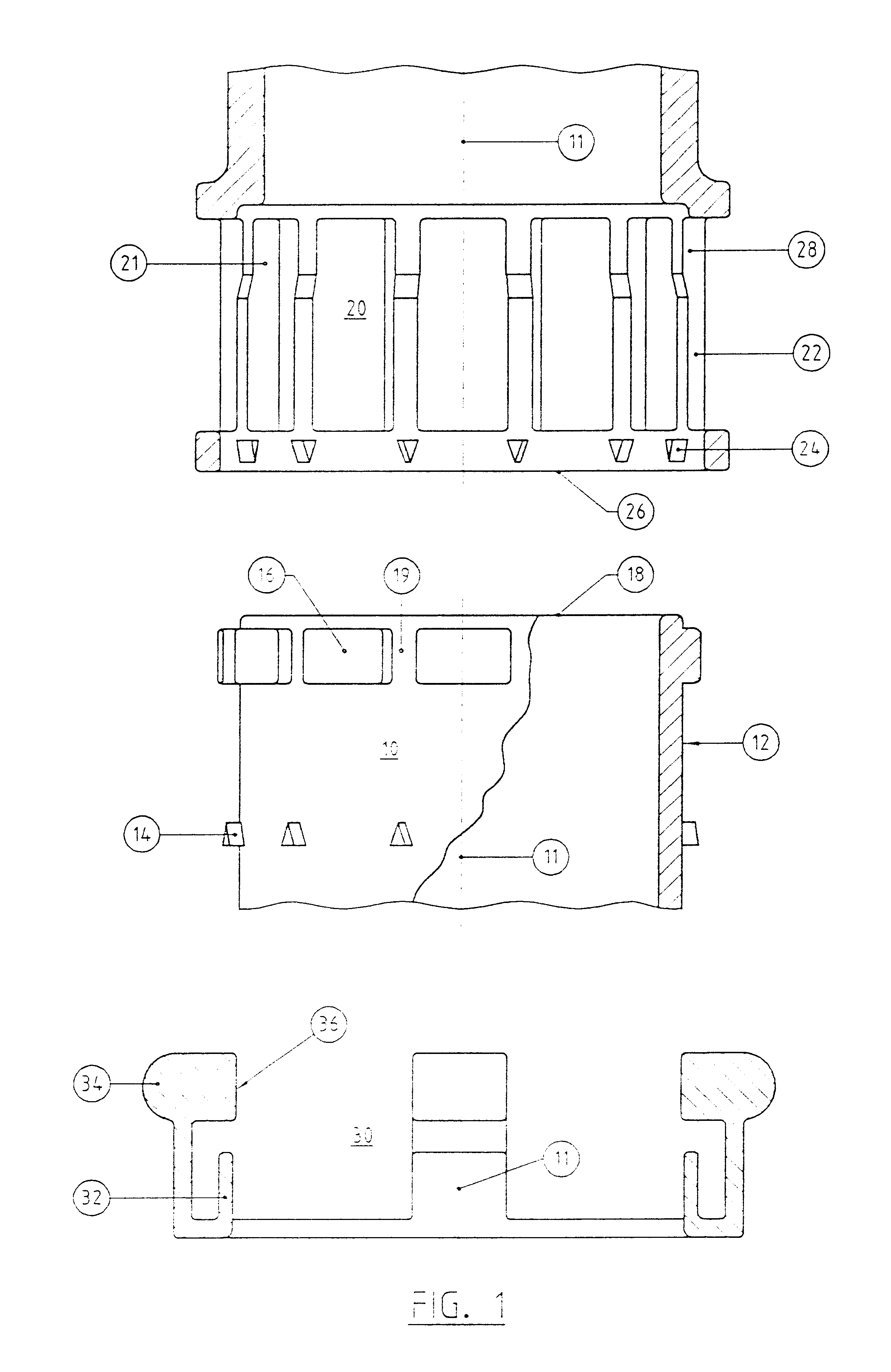
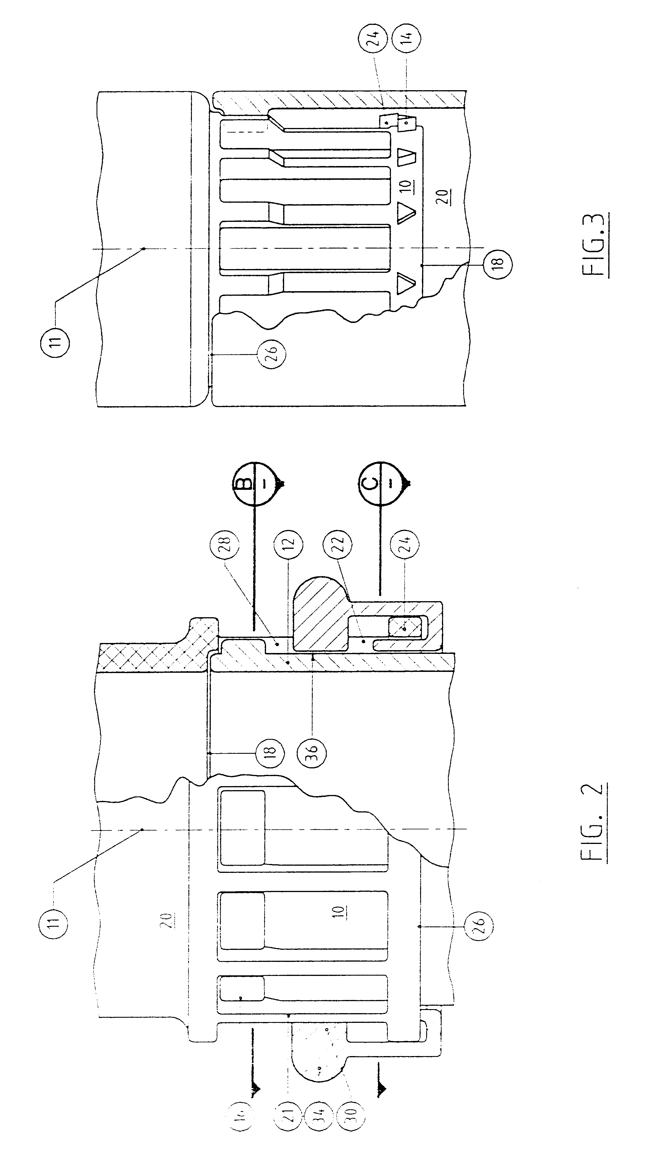
Referring generally to FIGS. 1 to 5, there is shown a preferred form of connector the male member 10 includes a cylindrical outer wall 12, the surface of which is provided with locating / guiding means in the form of a series of male guide projections 16 which are spaced around the outer circumference of the outer wall 12 so as to define gaps or male guide recesses 19 therebetween. In the embodiment depicted in FIG. 1, the male guide projections 16 are located proximate the outer end 18 of the male member 10.

Whilst the male member 10 and female member 20 depicted in FIG. 1 are hollow, it should be noted that the male member 10 may also be solid.

The corresponding female member 20 includes a cylindrical skirt (inner wall) 22, which is provided with locating / guide means in the form of female guide projections 28 which are located away from the open end or mouth 26 of the female member 20. In the embodiment depicted the female guide projections 28 extend in an axial direction down ...


PUM


Abstract

This invention provides a connector for coupling a male and a female component, the connector including a member for locating the female component with respect to the male component and a locking member for coupling the female component to the male component. The locking member rotates with respect to the locating member in order to provide for the coupling and uncoupling of the components.

Description

The present invention relates to a connector for coupling objects together, and in particular relates to a connector for the coupling of a male and female component by means of an improved snap fit type action.BACKGROUND TO THE INVENTIONThere are many forms of connectors for the coupling of male and female components by means of a snap fit action. Such connectors comprise one or more connecting elements such as lugs or projections on one component which engage upon or with the other component. Such connectors sometimes rely upon deformation of the connecting elements during the coupling process, or alternatively upon the radial movement of the connecting elements during the coupling process. However, whilst such connectors can provide for the easy coupling of the male and female components, the connectors may also be prone to being inadvertently uncoupled.It is therefore an object of the present invention to provide an improved connector for coupling male and female components which...

Claims


Application Information

Patent Timeline
Patent Type & Authority Patents(United States)
IPC IPC(8): F16L37/084F16L37/00F16L37/12
CPCF16L37/084Y10S285/921
Inventor GASPARINI, GIACOMO SALVATORE
Owner JOTT AUSTRALIA
Why Eureka
Try Eureka