In-line venturi

a venturi and tube technology, applied in water supply installation, process and machine control, instruments, etc., can solve the problems of requiring complex plumbing, expensive, bulky, and single tube can only operate over a narrow range of fluid flow rate, and achieve constant and consistent operation, increase the effect of venturi, and constant aspiration ra

Inactive Publication Date: 2001-06-26
ATI PROPERTIES
View PDF10 Cites 20 Cited by
  • Summary
  • Abstract
  • Description
  • Claims
  • Application Information

AI Technical Summary

Benefits of technology

Another aspect of the invention provides a fluid flow control means which divides the fluid flow stream into a first stream which flows through the venturi tube and a second stream which flows around the venturi tube. The fluid flow control means is adapted to allow the back pressure within the venturi tube (which increases as the fluid flow rate increases) to force an increasing proportion of the flow stream to flow around the venturi tube in order to maintain a relatively constant aspiration rate within the venturi tube. This permits a relatively constant and consistent operation of the venturi tube over a wider range of fluid flow rates by increasing the flow rate of the second stream rather than increasing the flow rate of the first stream as the rate of the fluid flow stream increases.
In another aspect, the invention provides means for inducing a vortex in the second stream, preferably at or near the venturi tube outlet. This induced vortex produces a surprising increase in the venturi effect and reduces backpressure at any given fluid flow rate. In addition, the vortex increases the mixing action of the first and second streams. The induced vortex permits more constant flow rates in the first stream, yielding a satisfactory venturi effect over a wider range of fluid flow rates.

Problems solved by technology

One of the major problems associated with conventional venturi tubes is that any single tube can only operate over a narrow range of fluid flow rates.
Conventional bypass systems have several limitations including being costly, bulky and requiring complex plumbing which hinders easy installation in association with an existing fluid conduit.

Method used


Image

  • In-line venturi
  • In-line venturi
  • In-line venturi

Examples


Embodiment Construction

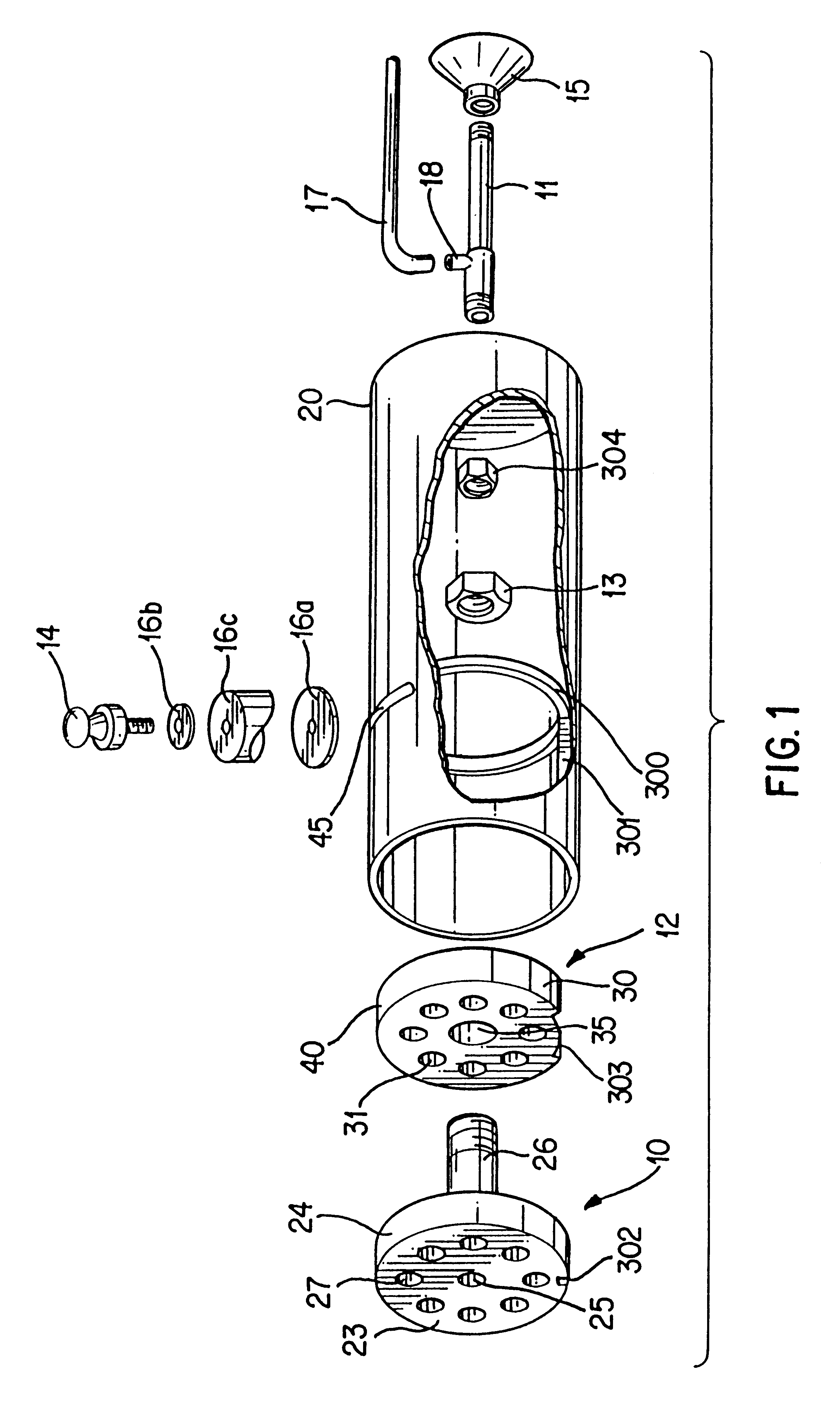
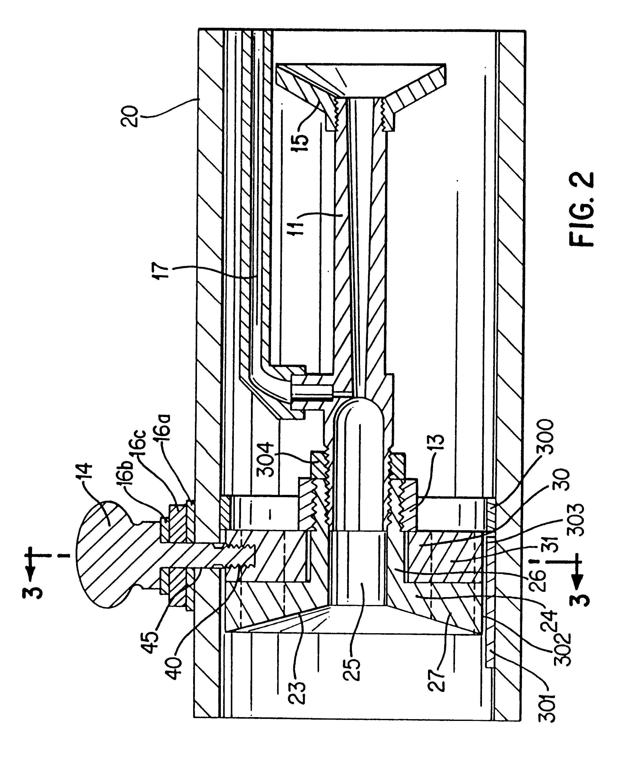
FIGS. 1 and 2 show a preferred embodiment of the present invention installed within a conduit 20 through which a fluid can flow in a stream. In this embodiment a venturi support body, shown generally at 10, comprises a disc 24 which is sized to closely fit within cylindrical conduit 20. Any suitable means for securing disc 24 in a sealing relationship within the conduit 20 can be used (for example, a suitable adhesive, a shoulder, or disc 24 and conduit 20 can be molded as one integral unit). The securing means should be sufficiently strong to withstand the pressures of the fluid flow stream and to keep the support body in sealing relationship with the conduit. In the preferred embodiment shown in FIGS. 1 and 2, an inner seating ring 300, attached to the inside of conduit 20, prevents downstream movement of disc 24, while allowing withdrawal of the unit, in the upstream direction, for maintenance if necessary. A key 301, attached to the inside of conduit 20, fits through keyway 302 ...


PUM


Abstract

An apparatus for inserting a venturi tube having an inlet, an aspirator inlet and an outlet directly within a fluid flow stream, with the aspirator inlet not in contact with the fluid flow stream is disclosed. A plate having a first aperture leading to the venturi inlet, and a series of second apertures both supports the venturi within a conduit and divides the fluid flow stream into a first stream which flows through the venturi tube and a second stream which flows around the venturi tube. A variety of adjusting mechanisms are disclosed for varying the cross sectional area of the second apertures relative to the cross sectional area of the venturi tube. The apparatus is adapted to allow the back pressure within the venturi tube (which increases as the fluid flow rate increases) to force an increasing proportion of the flow stream to flow around the venturi tube in order to maintain a relatively constant aspiration rate within the venturi tube. The adjustment mechanisms disclosed include a second plate, similar to the first plate, which is manually rotated and a blocking ring which moves responsive to changes in rate of flow of the fluid flow stream.

Description

FIELD OF THE INVENTIONThe invention relates to a venturi tube apparatus.BACKGROUNDVenturi tubes are well known in the art for introducing a second fluid into a first fluid. Typically, the inlet of the venturi tube is attached to a conduit for the first fluid, and the second fluid is introduced through a second inlet, hereafter called an aspirator inlet, so that the combined fluid exits through the venturi's outlet. In operation, the gas or liquid to be introduced is sucked into the venturi through the aspirator inlet, as the fluid flows through the venturi tube. For a given venturi tube, the aspiration rate depends on the flow rate of the fluid which passes through the venturi inlet and the viscosity of the fluids.One of the major problems associated with conventional venturi tubes is that any single tube can only operate over a narrow range of fluid flow rates. This is in part because back pressure produced within the venturi increases greatly with increases in the fluid flow rate....

Claims


Application Information

Patent Timeline
Patent Type & Authority Patents(United States)
IPC IPC(8): G05D11/00
CPCG05D11/006Y10T137/0363Y10T137/87281Y10T137/87346Y10T137/87547Y10T137/87603Y10T137/87619Y10T137/87652
Inventor CONRAD, WAYNE ERNESTCONRAD, HELMUT GERHARDPHILLIPS, RICHARD STANLEYPHILLIPS, ANDREW RICHARD HENRYBOWMAN, GERALD EARLPRESTON, MICHAEL JOHN
Owner ATI PROPERTIES
Why Eureka
Try Eureka