Ice dispense system and method

a technology of dispense system and ice dispenser, which is applied in the field of ice dispensing, can solve the problems of reducing the operating time of the agitator and reducing the amount of ice pushed into the upper end of the chute, and achieves the effects of convenient daily removal for cleaning, quick release and indexing tab features, and convenient and intuitive us

Inactive Publication Date: 2008-06-05
IMI CORNELIUS
View PDF19 Cites 7 Cited by
  • Summary
  • Abstract
  • Description
  • Claims
  • Application Information

AI Technical Summary

Benefits of technology

[0021]The front cover of the ice chute incorporates quick release and indexing tab features that allow the user to use one hand to remove the cover for cleaning. This ensures that the cover can conveniently be removed daily for cleaning, and the quick release and indexing tab features are easy and intuitive to use.
[0022]To open and dose an ice dispense gate at a lower ice outlet opening from the ice chute, a pneumatics system is used and incorporates a dual-acting pneumatic cylinder that is activated to both open and close the ice dispense gate. The cylinder is mounted in a horizontal orientation at the lower end of the ice chute, so that any moisture or condensate originating from the ice chute cannot drip onto and run down the rod or nose of the cylinder. To avoid injury to the user, the pneumatic system has a protective cover to protect a user's fingers from accidentally coming into contact with the cylinder. In addition, another safety feature consists of providing the ice dispense gate with a size and configuration so that, when it is closed, a gap exists between it and the ice chute interior to ensure that if the gate closes while the user's fingers are in the lower end of the ice chute, severe damage to the user's fingers will not occur.
[0023]As a further safety feature for the pneumatic system, a pressure relief valve is upstream of the air supply to the pneumatic cylinder to prevent the cylinder from exerting a closing force on the ice dispense gate that is greater than an allowable predetermined closing force, thereby to further mitigate the potential for severe damage to a user's fingers. Also, the pneumatic system is provided with a manual bypass system, so that should the system fail in the closed position of the ice dispense gate, the user can manually bleed air out of the system and enable the ice dispense unit to be manually operated for continued dispensing of ice to customers.
[0024]The ice portion and control system is particularly adapted for use on an ice and beverage dispensing machine to ensure constant and consistent delivery of ice and beverages to customers. The system incorporates unique features that provide a greater ability to conveniently and thoroughly clean the system and an improved ergonomic design to enable better access to beverage valves of the ice / beverage dispenser and the ice chute. Such ergonomic design features include a one piece merchandiser that accommodates attachments to the merchandiser, which attachments can be removed to allow the exposed surface of the merchandiser to be readily cleaned with no dead spots; easier access to and better visibility of the beverage dispensing valves and ice chute with no intrusions; and a visually less intrusive design with a unique front side profile.
[0025]Further, as the ice chute and the ice dispense point are more easily viewed by a user, beverage and / or ice dispenses may be made with less spillage and waste and, therefore, greater profit and customer satisfaction.
[0026]Ease of service and customer ease of use are increased by a cup lid dispenser which, unlike prior cup lid dispensers, does not obscure the ice and beverage dispense area. To achieve this result, the cup lid dispenser is mounted in front of the dispense area and is angled or sloped from the top downwardly away from the customer, thus increasing his / her view of the ice and beverage dispensing operation. Further, the sloped cup lid dispenser is fastened to the dispenser in a manner that enables it to be easily removed for service and or cleaning of the cup lid dispenser and / or ice and beverage dispenser. The cup lid dispenser is somewhat like that shown in co-pending U.S. patent application Ser. No. 07 / 204,423, filed Jun. 9, 1988, the teachings of which are specifically incorporated by reference herein.

Problems solved by technology

Increasing such constant results in an increase in the time spent operating the agitator to push ice from the storage bin into the upper end of the chute to refill the chute, while decreasing the constant decreases agitator operating time and thereby decreases the amount of ice pushed into the upper end of the chute.

Method used


Image

  • Ice dispense system and method
  • Ice dispense system and method
  • Ice dispense system and method

Examples


Embodiment Construction

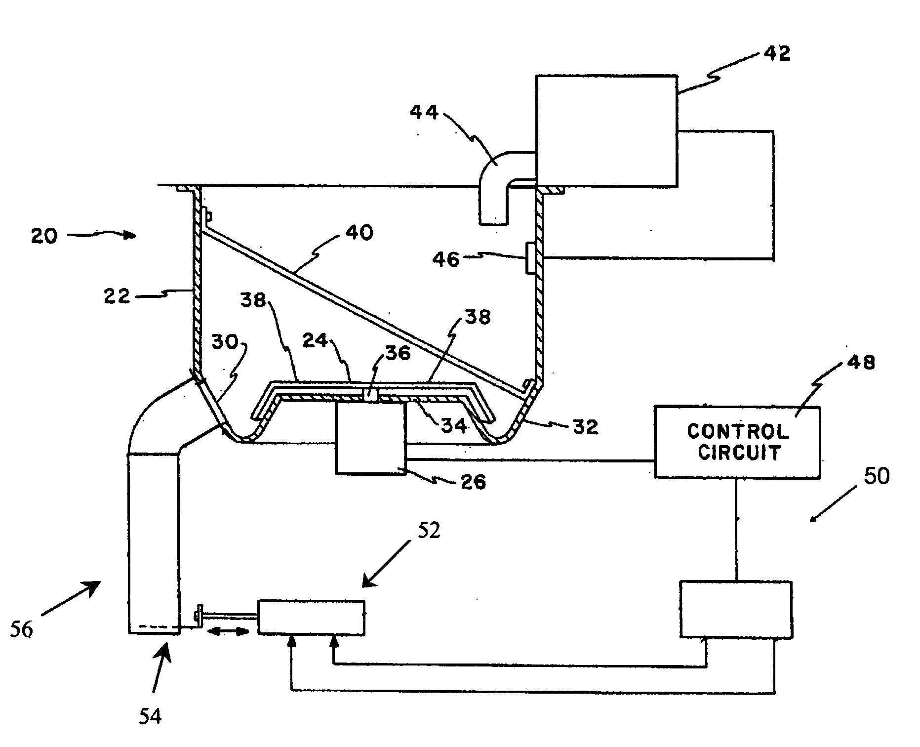
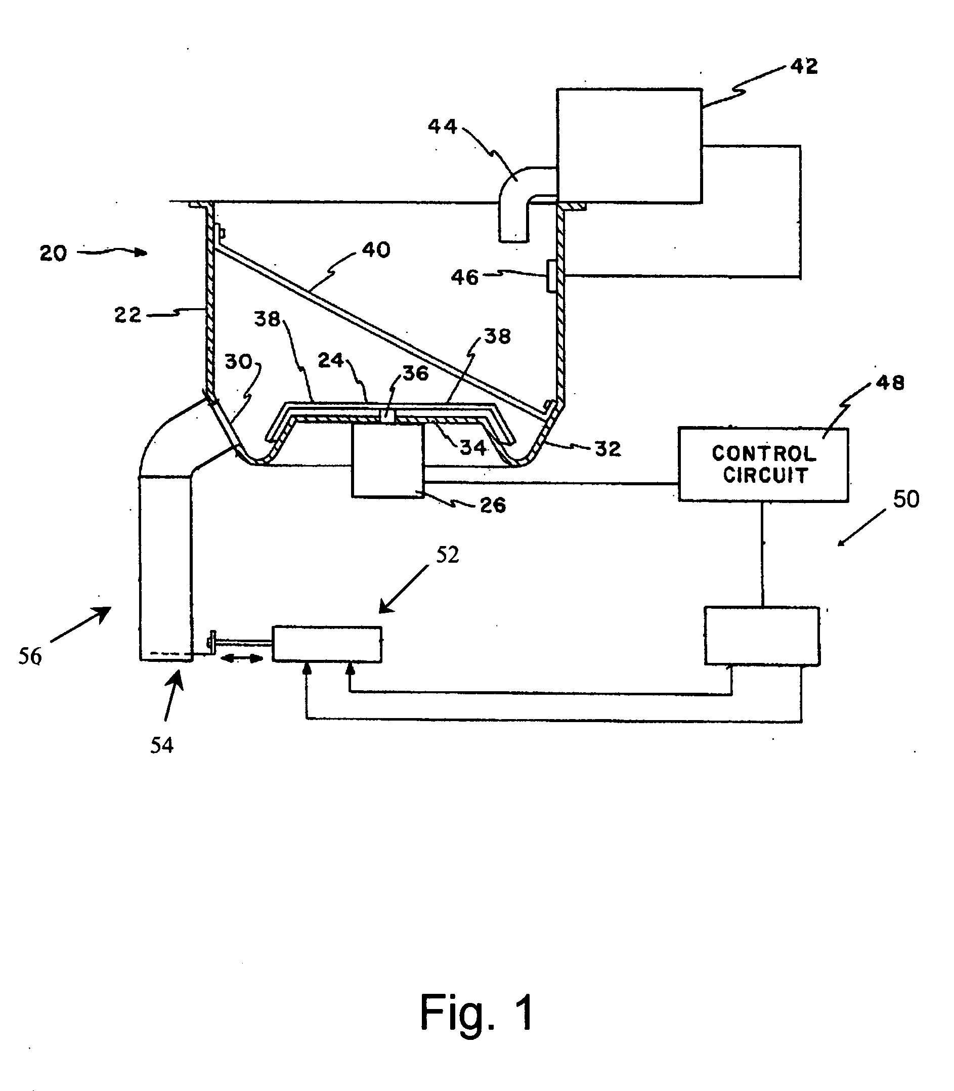
[0048]FIG. 1 is a simplified representation of an ice dispenser, indicated generally at 20, of a type with which the teachings of the present invention may advantageously be used. The ice dispenser includes an ice bin 22 for storing a large quantity of crushed, cracked, flaked or cubed ice, a rotary impeller or agitator 24 in the bin and driven by an electric motor 26, and a lower ice outlet passage 30 in the bin accommodating discharge of ice from the bin upon rotation of the agitator. The bottom of the bin may be formed in an annular trough 32 in which the ice discharge passage 30 is formed a short distance above the bottom of the trough, and the trough is provided at its bottom with melt water drain holes (not shown), so that only discrete particles of relatively dry ice move through the passage. The bottom of the bin is closed by an end wall 34, so that ice to be discharged gravitates into and is confined within the trough as it is moved by the agitator 24 to and through the ice...


PUM


Abstract

An ice dispense system for an ice dispenser is characterized by a chute having an ice receiving upper end in communication with an ice bin outlet passage and an ice dispensing lower end. Beginning with the chute filled with ice and its lower end closed, to dispense a selected quantity of ice, the chute lower end is opened for one of a plurality of different time periods, where each individual time period of the plurality is of a duration to dispense from the chute an associated predetermined quantity of ice. In response to dispensing ice from the chute, an agitator in the bin is operated for one of a plurality of different time periods, where each individual time period of the plurality is of a duration to move through the bin outlet passage and into the upper end of the chute an amount of ice substantially equal to that dispensed. The ice dispensing system is provided with an improved user interface and user programmable features.

Description

[0001]This application claims benefit of provisional application Ser. No. 60 / 853,856, filed Oct. 24, 2006.FIELD OF THE INVENTION[0002]The present invention relates to ice dispensing, and in particular to an improved apparatus for and method of dispensing selected quantities of ice.BACKGROUND OF THE INVENTION[0003]It is known to provide ice dispensers that dispense selected quantities of ice. One such ice dispenser forms the subject matter of U.S. Pat. No. 4,921,149, which is assigned to IMI Cornelius, Inc., the assignee of the present application and the teachings of which patent are specifically incorporated herein by reference. Said patent teaches an ice portion control for an ice dispenser in which a chute has an upper end into which ice is introduced and a lower end from which ice is dispensed. A dispensing gate normally closes the lower end of the chute, and with the chute filled with ice, to vend a desired quantity of ice, the dispensing gate is opened for a selected one of a ...

Claims


Application Information

Patent Timeline
Patent Type & Authority Applications(United States)
IPC IPC(8): B67D5/08F25C1/00G04C23/00B67D7/08
CPCF25C5/187F25C5/007F25C5/24
Inventor NJAASTAD, DAVID K.IVANCEVIC, DUSAN N.LEAVER, DANIEL C.JABLONSKI, THADDEUS M.DUKE, BASSEY E.
Owner IMI CORNELIUS
Why Eureka
Try Eureka