System for calibration of an industrial robot and a method thereof

a technology for industrial robots and calibration methods, applied in the direction of electrical programme control, program control, instruments, etc., can solve the problems of time-consuming and expensive, interested in investing in expensive measuring equipment, and need educated people, so as to eliminate the need of expensive measuring equipment and be easy and intuitive to use.

Inactive Publication Date: 2010-07-13
ABB (SCHWEIZ) AG
View PDF6 Cites 27 Cited by
  • Summary
  • Abstract
  • Description
  • Claims
  • Application Information

AI Technical Summary

Benefits of technology

[0006]The object of the present invention is to provide robot calibration, which eliminates the need of expensive measuring equipment and which is easy and intuitive to use.
[0008]The method is very easy to use and does no require any expert knowledge. The measurements on the geometrical structure are made simply by moving the measuring tip over the surface of the geometrical structure while the actuator positions are stored. Preferably, the measuring tip is moved with the robot in force manipulation mode. In the force manipulation mode the robot control unit reads force- and torque values from a force / torque sensor mounted between the tool (in this case the measuring tip or a reference object) and the tool flange. These values are used by the control unit to calculate the actuator movements needed for the robot to follow the movements that the operator wants the tool to have, with respect to the forces and torques that the operator gives to the tool. The actuator positions are measured with existing measuring devices, for example encoders or resolvers, of the robot. Thus, no expensive measuring equipment is needed. This method does only require a measuring tip and possibly a simple geometrical structure and accordingly is inexpensive.
[0010]According to an embodiment of the invention, the geometrical structure is a part of the robot. In this embodiment, the geometry of the robot itself is used. It is advantageous to use a part or parts of the robot structure as the geometrical structure, since there already exist CAD-models for the robot parts, which CAD-models were produced during manufacturing of the robot. Another advantage is that no extra geometrical structure is needed.
[0012]According to an embodiment of the invention the robot comprises a wrist having a tool flange and the measuring tip is mounted on the tool flange of the wrist. Using a wrist, movable in one or more degrees of freedom, makes it possible to reach more measuring points on the surfaces of geometrical structures and thus to improve the determination of the kinematic parameters.
[0013]According to an embodiment of the invention, the method further comprises notifying the user if it is not possible to determine all kinematic parameters based on the stored positions. Then, the operator has to make measurements with the measuring tip over more surfaces in order have the robot calibrated. This embodiment is advantageous since it gives the operator a chance to provide the system with more measurements until it is possible to determine the kinematic parameters needed for the robot tasks with sufficient accuracy.

Problems solved by technology

Thus, problems with prior art calibration methods are that they require educated people, are time-consuming and expensive.
However, an end-user having few robots is not interested in investing in expensive measuring equipment.

Method used


Image

  • System for calibration of an industrial robot and a method thereof
  • System for calibration of an industrial robot and a method thereof
  • System for calibration of an industrial robot and a method thereof

Examples


Embodiment Construction

[0037]In the following, examples of the method and system according to the invention will be described in connection with a parallel kinematic manipulator. However, the invention is applicable also for other types of manipulators such as serial kinematic manipulators.

[0038]A parallel kinematic manipulator (PKM) is defined as a manipulator comprising at least one stationary element, a movable element, denoted a platform, and at least two arms. Each arm comprises a link arrangement connected to the movable platform. Each arm is actuated by a driving means preferably arranged on the stationary element to reduce the moving mass. These link arrangements transfer forces to the movable platform. For a fully built-up parallel kinematic manipulator for movement of the platform with three degrees of freedom, e.g. in directions x, y and z in a Cartesian system of coordinates, three parallel-working arms are required.

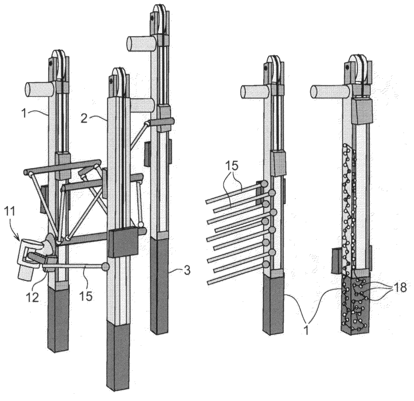
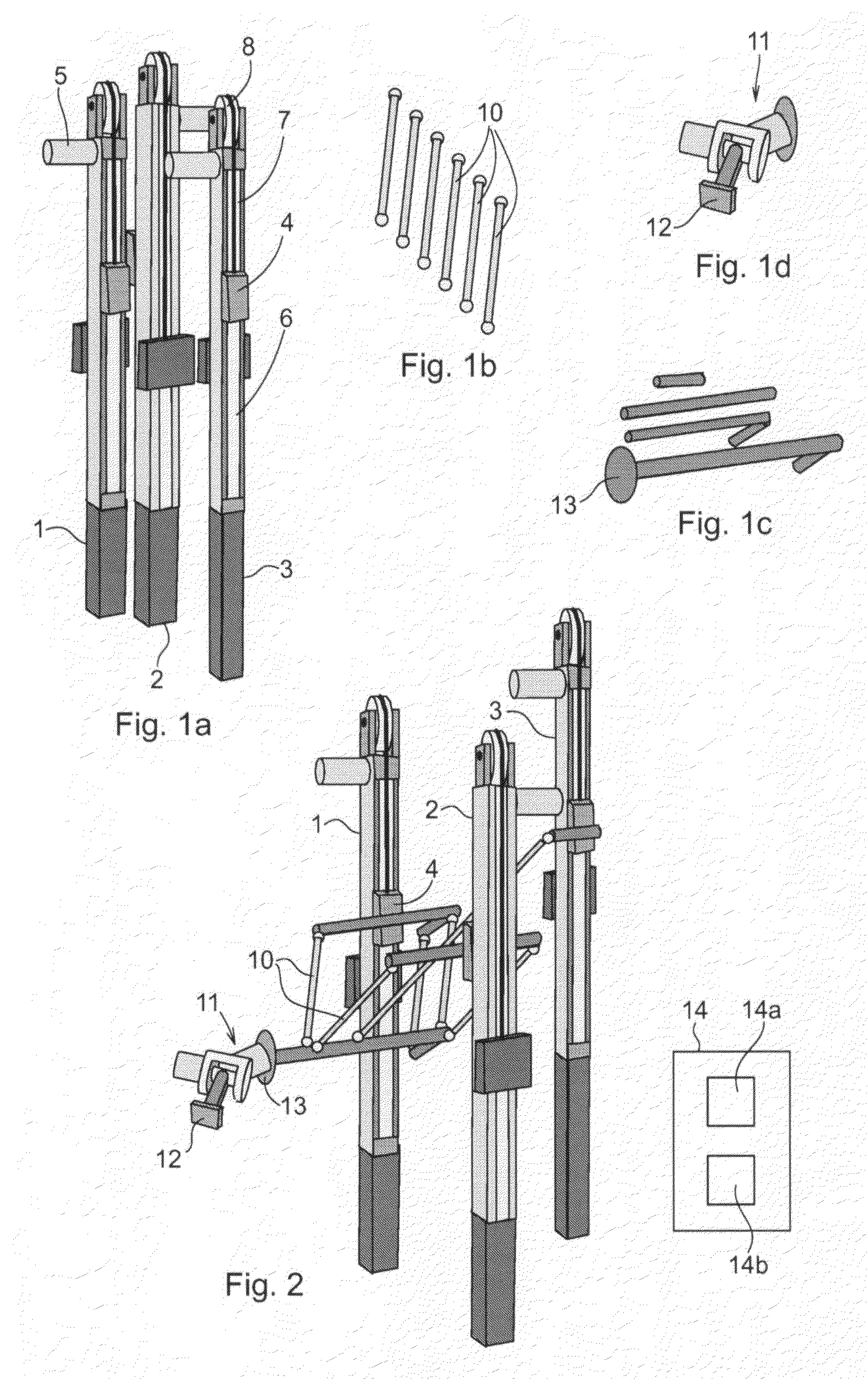
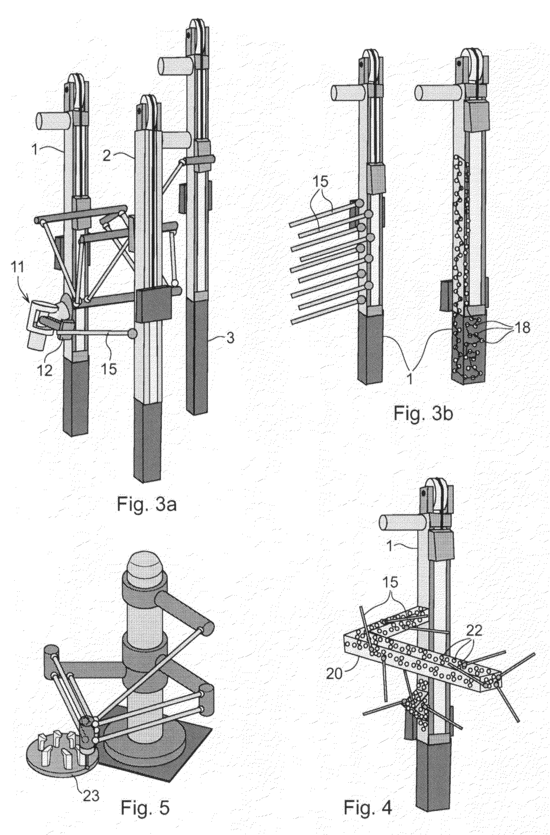
[0039]FIGS. 1a-c show examples of robot components which can be delivered dire...


PUM


Abstract

A method for calibration of an industrial robot including a plurality of movable links and a plurality of actuators effecting movement of the links and thereby of the robot. The method includes mounting a measuring tip on or in the vicinity of the robot, moving the robot such that the measuring tip is in contact with a plurality of measuring points on the surface of at least one geometrical structure on or in the vicinity of the robot, reading and storing the positions of the actuators for each measuring point, and estimating a plurality of kinematic parameters for the robot based on a geometrical model of the geometrical structure, a kinematic model of the robot, and the stored positions of the actuators for the measuring points.

Description

CROSS-REFERENCE TO RELATED APPLICATIONS[0001]This application claims priority to U.S. provisional patent application 60 / 656,543 filed 28 Feb. 2005 and is the national phase under 35 U.S.C. §371 of PCT / EP2006 / 060140 filed 21 Feb. 2006.FIELD OF THE INVENTION[0002]The present invention relates to a system and a method for calibration of an industrial robot including a plurality of movable links and a plurality of actuators effecting movement of the links and thereby of the robot. The method is suitable for calibration of any type of robot, such as a parallel kinematic robot or a serial kinematic robot.PRIOR ART[0003]An industrial robot includes a manipulator and a control unit having means for controlling the movements of the manipulator. There are different types of manipulators, such as a serial kinematic manipulator and a parallel kinematic manipulator. If the robot is a serial kinematic robot the links are also denoted arms. The manipulator includes a plurality of movable axes. The...

Claims


Application Information

Patent Timeline
Patent Type & Authority Patents(United States)
IPC IPC(8): G05B19/04
CPCB25J9/1623B25J9/1692G05B2219/39032G05B2219/39053G05B2219/40267
Inventor BROGARDH, TORGNY
Owner ABB (SCHWEIZ) AG
Why Eureka
Try Eureka