
Control and a control arrangement

a control arrangement and control technology, applied in the field of control, can solve the problems of difficulty in using joystick-like controls in portable electronic devices, difficulty in intuitive and easily adopted controls, and inability to control the presentation of three-dimensional graphics, etc., and achieve the effect of convenient, easy and intuitive us

Active Publication Date: 2009-03-24
NOKIA TECHNOLOGLES OY
View PDF7 Cites 25 Cited by
  • Summary
  • Abstract
  • Description
  • Claims
  • Application Information

AI Technical Summary

Benefits of technology

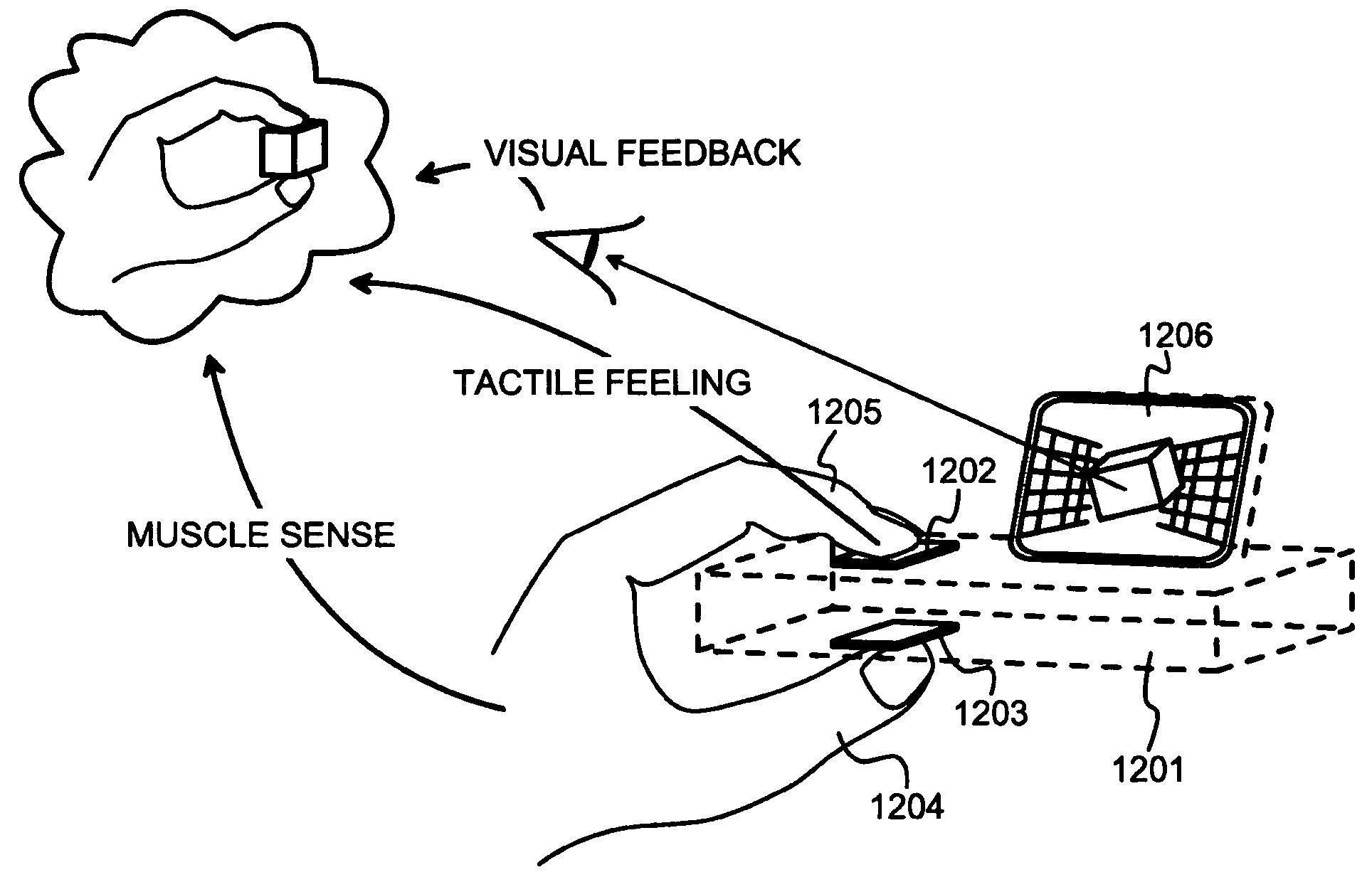
The invention provides a control and control arrangement for controlling the presentation of graphics, particularly three-dimensional graphics, on an electronic device. The control is intuitive and easy to use, with a first control surface located on one side of the device and a second control surface located on the other side. The device has detectors that can jointly detect how the first and second control surfaces are manipulated, and the information about the manipulation is used to generate the control signals. The control arrangement can be adapted for different electronic devices and control modes. The invention also provides a handheld electronic device with a first and second control surface, which can be used to control the presentation of graphics.

Problems solved by technology

A major problem related to three-dimensional graphics is the need for intuitive and easily adopted controls.
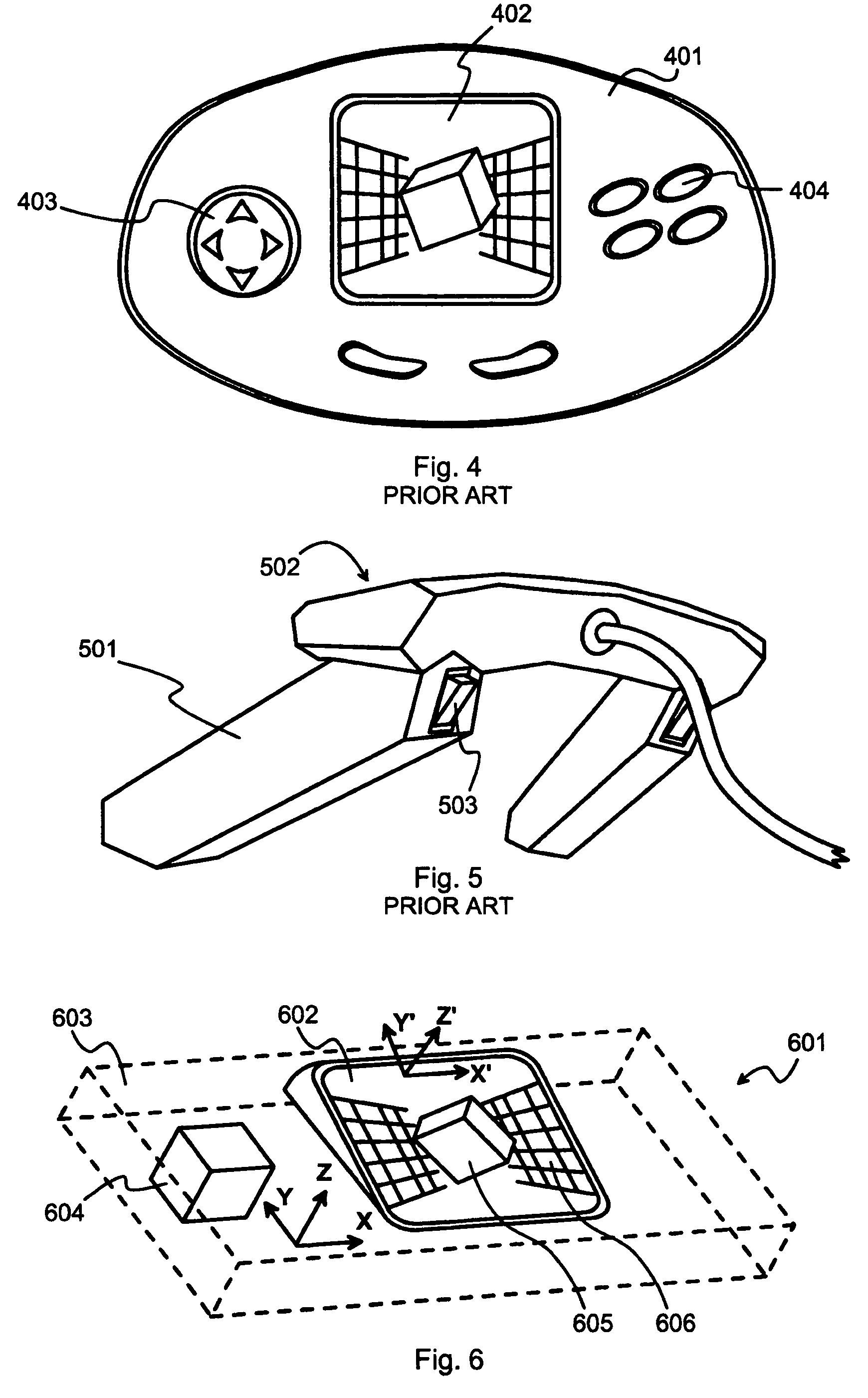
The intuitiveness of the controls known from prior art in controlling the presentation of three-dimensional graphics is modest even at its best.
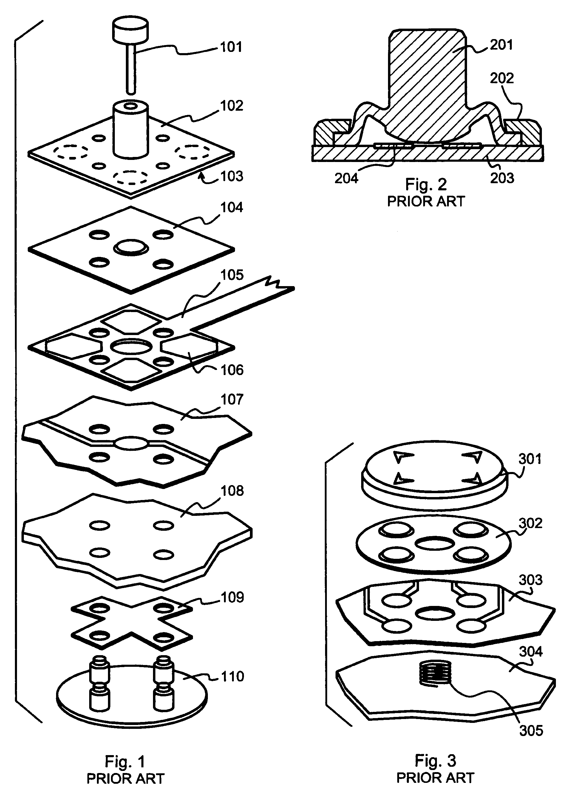
Using joystick-like controls in portable electronic devices may become problematic if the joystick protrudes remarkably out of the overall appearance of the device.
Another problem of prior art is that full three-dimensional control of displayed objects usually requires the user to manually select between available control modes.

Method used


Image

  • Control and a control arrangement
  • Control and a control arrangement
  • Control and a control arrangement

Examples


Embodiment Construction

[0086]The exemplary embodiments of the invention presented in this patent application are not to be interpreted to pose limitations to the applicability of the appended claims. The verb “to comprise” and its derivatives are used in this patent application as open limitations that do not exclude the existence of also unrecited features. The features recited in depending claims are mutually freely combinable unless otherwise explicitly stated. Aspects of the invention are described in more detail under the following subheadings.

Principle of a “Control Cube”

[0087]A unique feature of the human hand is its ability to perform the key pinch grip. A most natural way of grabbing a three-dimensional object of the size of a sugar lump is to grasp it between the thumb and another finger, most typically the index or middle finger. A person examining an object of that size would take it into a key pinch grip and use the muscles and joints in his fingers, wrist and forearm to move and rotate the o...


PUM


Abstract

Control signals for a process displaying graphical objects in a display are generated with a first control surface, a second control surface and detector means. The first control surface is available for manipulation with a thumb of one hand on one side of a hand-held electronic device. The second control surface is adapted for manipulation with another finger of the same hand. It is located on a different side of the hand-held electronic device. The detector means jointly detect how the first and second control surfaces are manipulated, and convey information about detected manipulation of the first and second control surfaces further to generation of the control signals.

Description

TECHNICAL FIELD[0001]The invention is generally related to the technical field of controls that constitute a part of the user interface of an electronic apparatus and offer a human user the possibility of generating commands and input information through exerting a force at a control. Especially the invention relates to controls that provide an intuitive and easily adopted way of controlling three-dimensional graphics.BACKGROUND OF THE INVENTION[0002]The increasing processing power of electronic devices such as computers, game consoles, personal digital assistants (PDAs) and cellular radio terminals has evoked a trend towards using more and more three-dimensional graphics. Although at the time of writing this description an almost exclusive majority of display devices are two-dimensional screens, it is possible to make them show three-dimensional graphics by utilising perspective and shadows, increasing blurredness with increasing observation distance, and using other kinds of graph...

Claims


Application Information

Patent Timeline
Patent Type & Authority Patents(United States)
IPC IPC(8): G09G5/08G09G5/00
CPCG06F3/0338G06F3/03547G06F3/0487
Inventor PIHLAJA, PEKKANOUSIAINEN, JARIKESKI-JAKARI, TURO
Owner NOKIA TECHNOLOGLES OY
Learn More