Tape dispenser

a dispenser and tape technology, applied in the field of tape dispensers, can solve the problems of inability to accurately measure the visual assessment, the tape length is either too long or too short, and the tape may twist or crinkle, etc., and achieve the effect of precisely cutting the correct length of tap

Inactive Publication Date: 2006-07-18
STEINBERGER ROBERT
View PDF15 Cites 28 Cited by
  • Summary
  • Abstract
  • Description
  • Claims
  • Application Information

AI Technical Summary

Benefits of technology

[0023]It is an object of this invention to provide a tape dispenser which permits the application of an adhesive tape to a surface directly from the dispenser using only one hand to accurately position the tape at the proper location on the substrate and precisely cut the correct length of tape to be used.
[0024]It is yet another object of this invention to provide a tape dispenser capable of accurately aligning the tape on the surface to which it is to be applied, simultaneously pressing it into adhesive contact with such surface and then accurately cutting off the precisely desired length.
[0027]An additional object of this invention is to provide a low-cost tape dispenser wherein all parts, both static and moving, are simply constructed and compactly contained.
[0029]It is a further object of this invention to provide a tape dispenser that can be used for many type taping operations, such as taping paper together or as packing tape, is easy and intuitive to use and may be used with tape having an adhesive surface on both sides.

Problems solved by technology

Such visual assessment is rarely accurate and the tape length severed is either too long or too short.
Also, in transporting the length of tape to the point-of-use, the tape may twist or crinkle leading to an untidy package closure or letter seal.
It is thus very difficult through the use of conventional tape dispensers to get the exact length of adhesive tape that you need applied to the exact location you want.
Other problems associated with such prior art dispensers are that the end of the tape always remains in an exposed and the exposed cutting blade can be hazardous, particularly to children
Still further, such prior art tape dispensers are not well suited for single-handed use.
The dispensing becomes much more difficult if a longer piece of tape is required.
However, such a solution still suffers from the usual disadvantages of such dispensers.
Another disadvantage of these prior art dispensers is that the user must manually grip the adhesive surface of the tape at least once to dispense the tape.
This manual gripping reduces the adhesiveness of the tape and may transfer soil from the finger to the adhesive side of the tape.
The large heavy prior art tape dispenser that is suitable for some single-handed use cannot conveniently be positioned adjacent the object to which the tape is to be applied.
However, these dispensers are not well suited to direct application of the tape from the dispenser to the object being taped.
In particular, the tape can not be fed smoothly onto the surface and pressed into adhesive contact therewith.

Method used


Image

  • Tape dispenser
  • Tape dispenser
  • Tape dispenser

Examples


Embodiment Construction

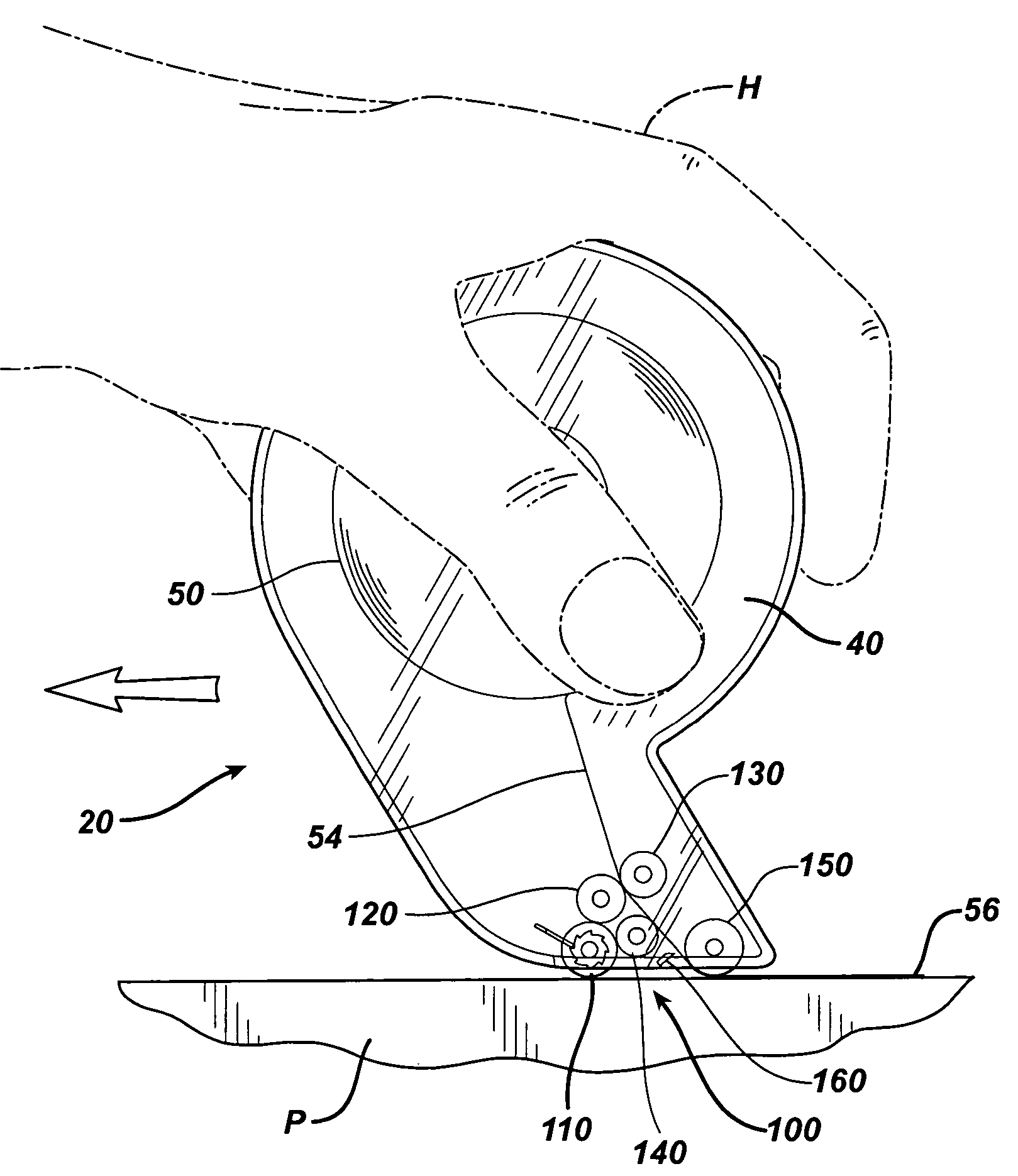
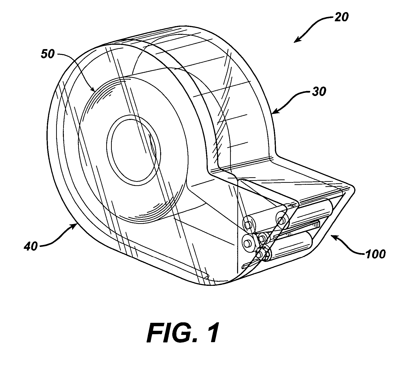
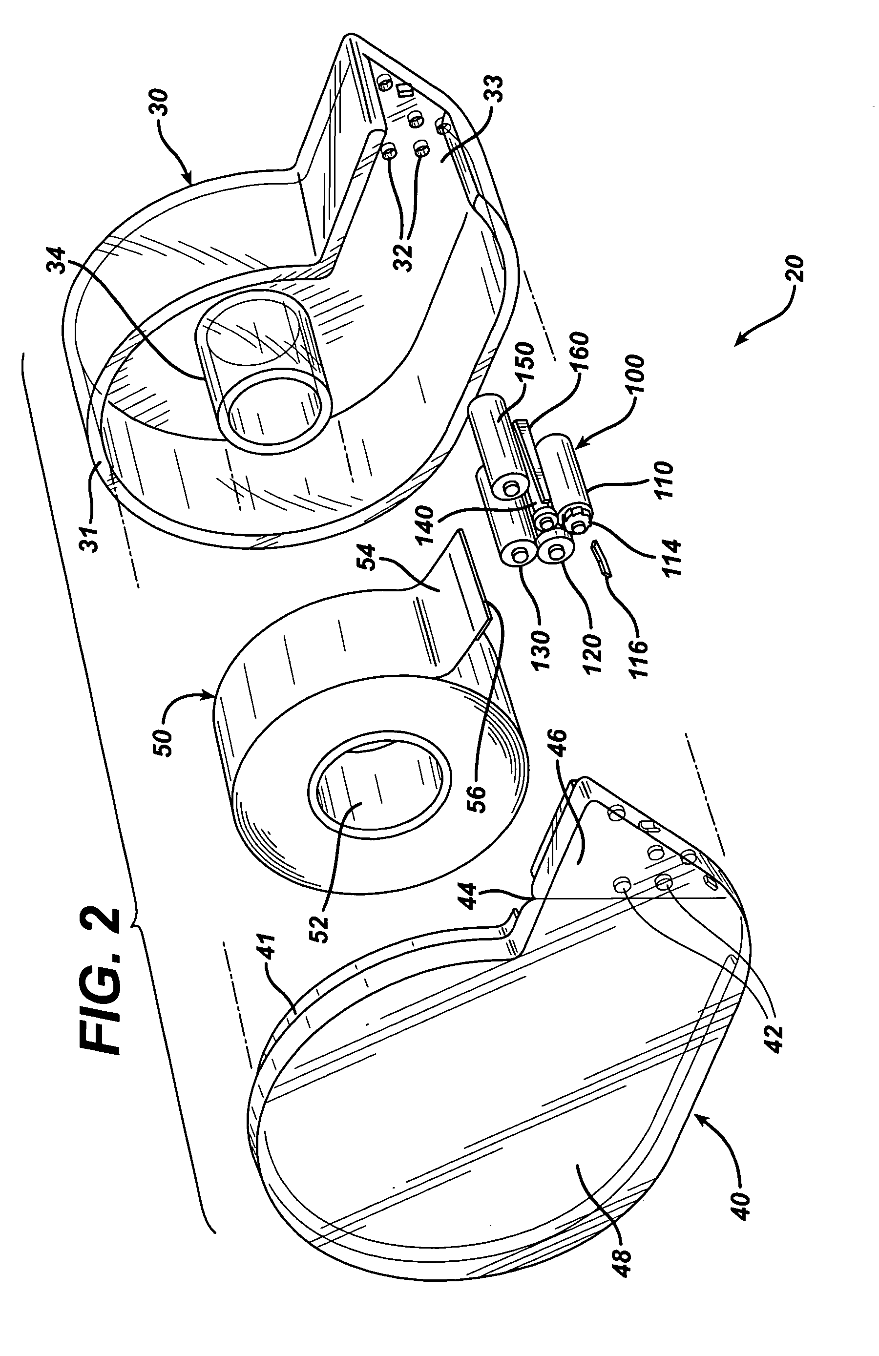
[0055]Referring to FIGS. 1–5, and in particular FIG. 2, the tape dispenser 20 is comprised of a right housing member 30 and a left housing member 40. Preferably the housing members are made of a plastic material, although any other type material is contemplated, e.g., metal, wood, ceramic. The dispenser 20 can have finger grips (not shown), possibly from rubber, placed at the appropriate places for ease of holding and using the dispenser 20 with the hand H.

[0056]The housing members 30, 40 house the roll of tape 50, the roller assembly 100 consisting of a plurality of rollers 110, 120, 130, 140, 150, and the knife blade 160. The roll of tape 50 has a tape core 52 and tape 54 wrapped around the core 52. Preferably the tape 54 has a pressure sensitive adhesive on one surface, although the use of a tape having a double sided adhesive is contemplated.

[0057]Referring to FIG. 2, housing member 30 mates with housing member 40 along lips 31 and 41 of the respective housing members 30,40. If ...


PUM

PropertyMeasurementUnit
pressure sensitiveaaaaaaaaaa
pressureaaaaaaaaaa
diameteraaaaaaaaaa

Abstract

A hand held tape dispenser for applying adhesive tape to a surface. The dispenser includes a housing for holding and dispensing a roll of tape and has a tape dispensing opening therein. A plurality of rollers are within the housing, the outer surfaces of which coact with each other and the tape to retain, guide and feed the tape through the opening. The outer surface of at least one of the rollers protrudes through the opening on one side thereof enabling frictional contact of the roller with the surface to be taped. When the tape dispenser passes over the surface in one direction the outer surface of the roller engages the surface and the tape causing it to roll and to coact and drive the other rollers. This causes the rollers to grip the surfaces of the tape and feed the tape through the opening enabling the tape to adhesively contact the surface and adhere thereto. The tape is cut off at the opening.

Description

RELATED APPLICATIONS[0001]This application is a continuation-in-part application of U.S. Ser. No. 10 / 408,134 filed on Apr. 7, 2003, now U.S. Pat. No. 6,971,431. The entire disclosure of this application is incorporated herein by reference.BACKGROUND OF THE INVENTION[0002]1. Field of the Invention[0003]This invention relates to a tape dispenser for applying pressure sensitive tape to a substrate surface. The dispenser is provided with a cutter for the tape and a plurality of rollers that smoothly and evenly feed and apply the tape onto the substrate.[0004]2. Description of the Related Art[0005]A roll of adhesive tape typically is mounted in a dispenser. The tape roll is usually a palm sized roll. Such a dispenser includes at least one side wall aligned substantially perpendicular to the axis of the spool. The side wall includes structure for rotatably maintaining the spool in the dispenser. Such a tape dispenser further includes an exposed metal or plastic serrated cutting blade. The...

Claims


Application Information

Patent Timeline
Patent Type & Authority Patents(United States)
IPC IPC(8): B32B37/00B65H35/00
CPCB65H35/0033B65H35/0073Y10T156/1793Y10T156/1365Y10T156/18Y10T156/1788Y10T156/1795Y10T225/285Y10T225/257
Inventor STEINBERGER, ROBERT
Owner STEINBERGER ROBERT
Why Eureka
Try Eureka