Telescopic sight for individual weapon with automatic aiming and adjustment

Inactive Publication Date: 2001-06-26
GUARY GABRIEL +1
View PDF14 Cites 205 Cited by
  • Summary
  • Abstract
  • Description
  • Claims
  • Application Information

AI Technical Summary

Problems solved by technology

Conventional sights have become limited for this type of shooting because at distances of from 1,000 to 1,500 meters, the evaluation error of the distance and interpretation of the drop of the bullet causes aiming errors.
However, the fact of displacing the point of aim relative to the central axis of sight of the rifle sight causes aiming errors due to distortion of th

Method used


Image

  • Telescopic sight for individual weapon with automatic aiming and adjustment
  • Telescopic sight for individual weapon with automatic aiming and adjustment
  • Telescopic sight for individual weapon with automatic aiming and adjustment

Examples


first embodiment

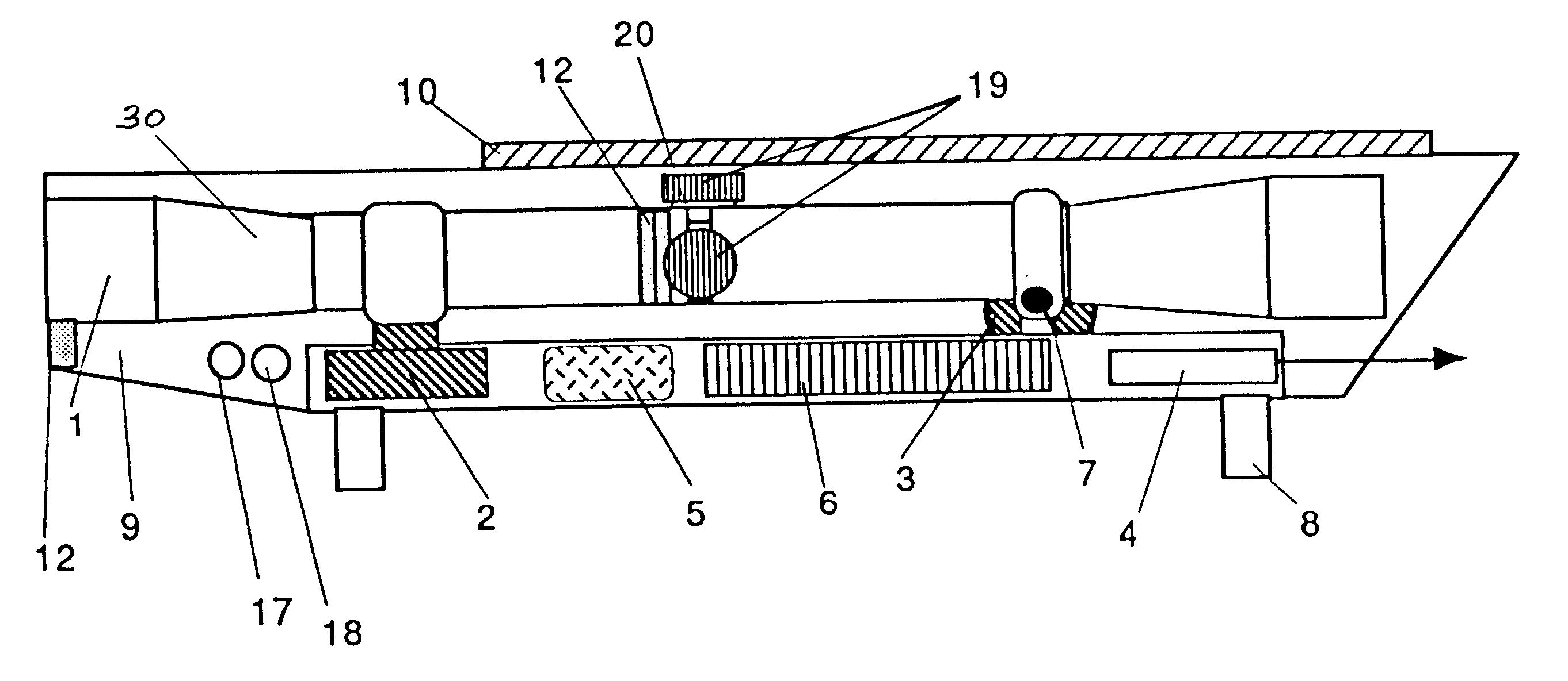
In a first embodiment illustrated in FIG. 1, the telescope sight 1 has a body 30 mounted on a support frame 8 and arranged in a protective cap 9, for example. The body 30 is mounted so that it can be pivoted about a horizontal pin 7, which is in turn joined to the frame 8. Fixed in this body in a manner known per se are optical means such as a lens and an eyepiece. The sight also has, mounted on the body 30, an initial reticle fitted with its adjusting knobs 19, a LCD screen 12 the purpose of which is to display information to the marksman (distance marksman / target, ammunition engaged, the power level of the batteries, a computer signal illustrated in FIGS. 6 and 7) and which is positioned in the vicinity of the reticle or eyepiece. An invisible laser beam rangefinder 4 and a computer 6, power batteries 5 which may or may not be rechargeable, and solar cells 10 are mounted on the support frame 8.

Two step micro-motors 2 and 3 are inserted between the support frame 8 and the body 30 s...

second embodiment

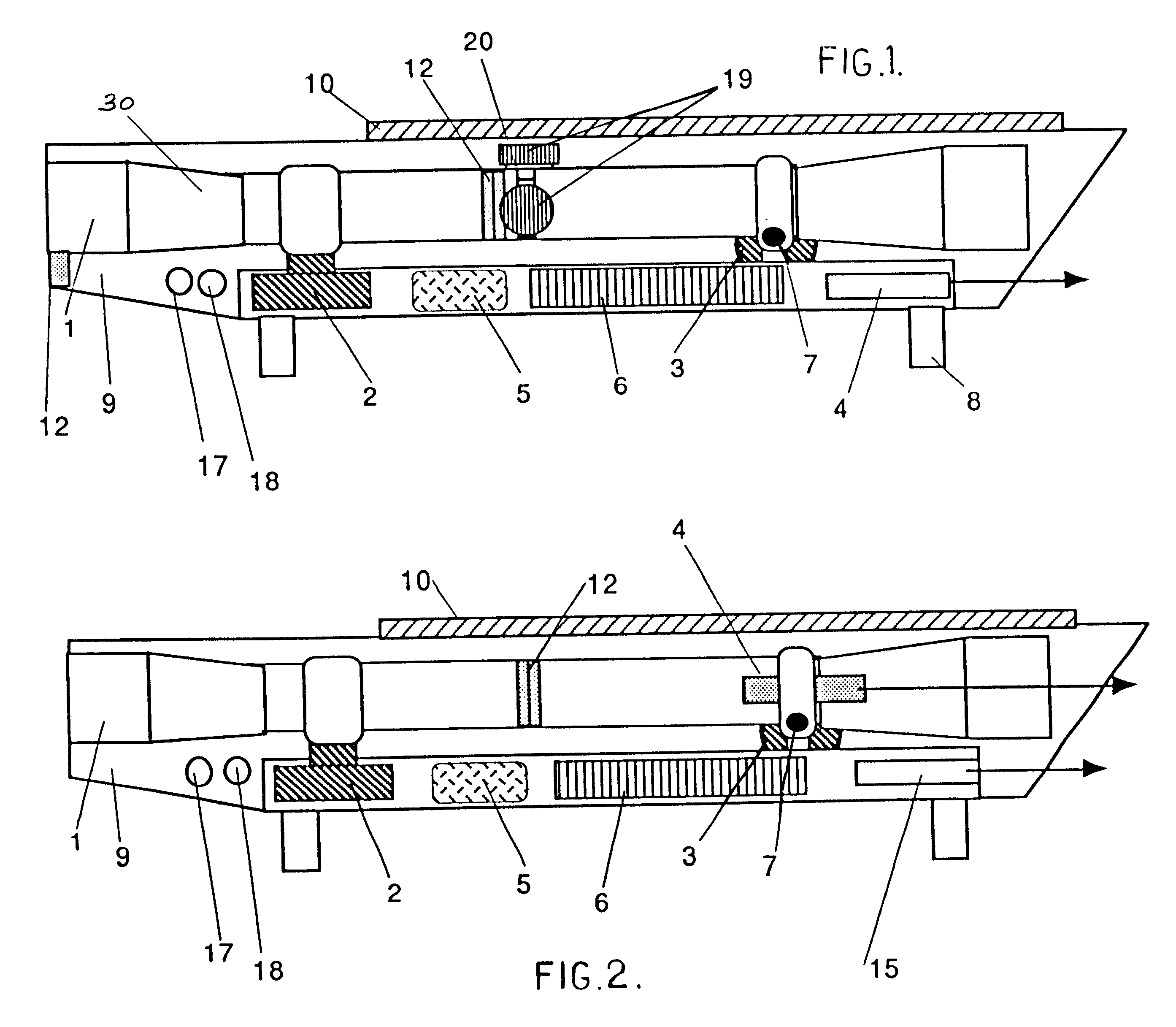
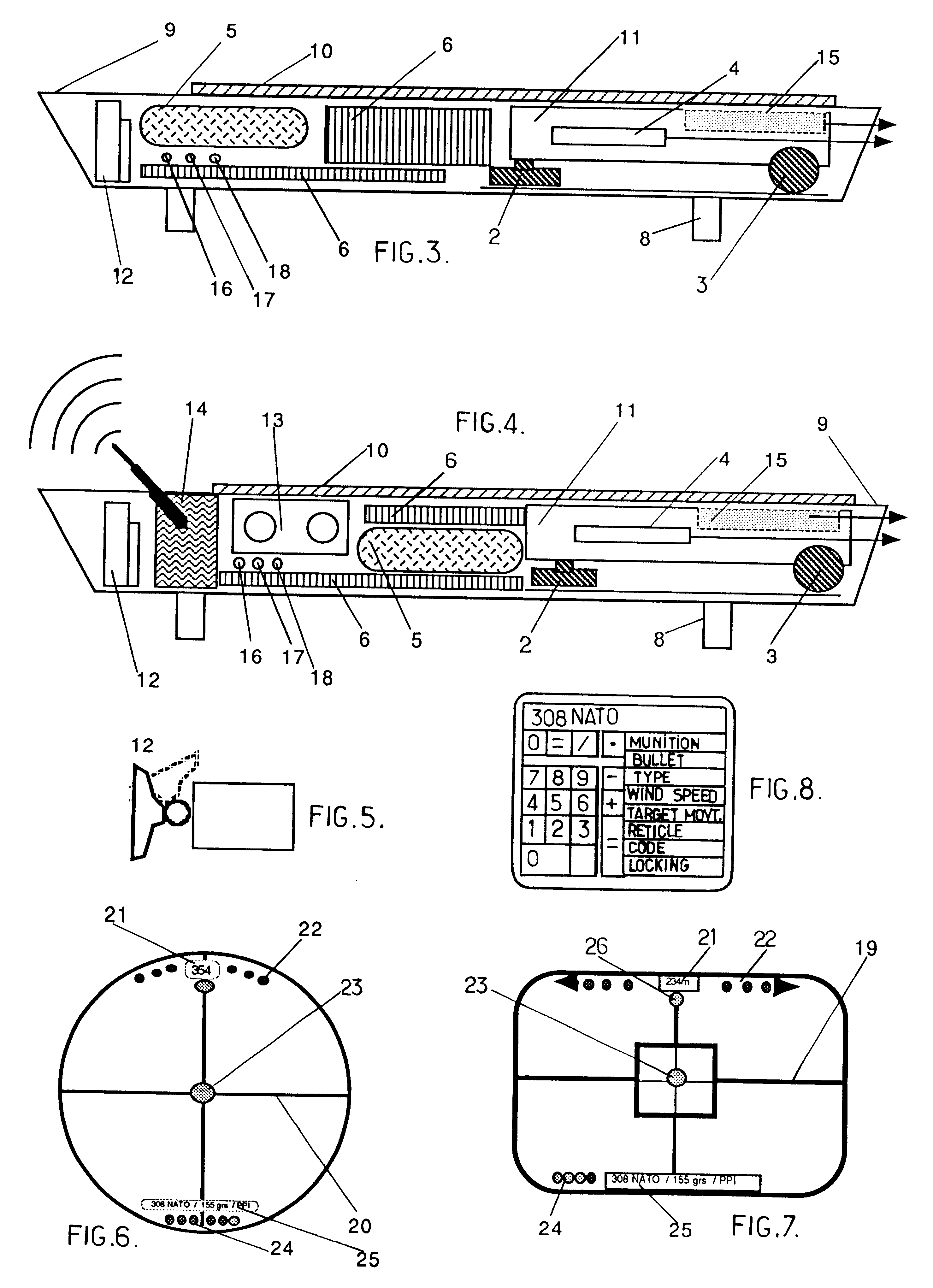
In a second embodiment, the telescope sight illustrated in FIG. 3 is also placed in a protective cap 9 and consists of a LCD screen 12 which can be oriented about its fixing (FIG. 5) for the purpose of viewing the target and displaying the sight reticle along with the information needed for firing purposes (FIGS. 6 and 7), a video camera 11 equipped with a motorised zoom, an invisible laser beam rangefinder 4, a visible laser beam pointer 15, a computer 6, a programming unit (FIG. 8), a sensor for detecting ammunition by bar coding, colorimetric or magnetic means, power batteries which may or may not be electrically rechargeable 5, solar cells 10, one or two step micro-motors 2 and 3 and a support 8 with two bases enabling the sight to be connected to the weapon. The computer memory stores different types of reticles which the marksman may select for display depending on his preference or the shooting conditions.

The unit comprising the camera, zoom, laser pointer and laser rangefind...


PUM


Abstract

The invention concerns a telescopic rifle sight for individual weapon equipped with at least one step micro-motor designed to vary the angle of the sight relative to the axis of the weapon and the initial axis of aim, thereby adequately varying the whole sight assembly and thus varying the original position of the sight reticle from the original point of aim to the required point of aim.

Description

The present invention relates to a telescope sight for an individual weapon enabling very high-precision firing for hunting, target shooting and anti-personnel fireBACKGROUND OF INVENTIONModern shooting techniques enable elite marksmen equipped with modern 12.7 m / m calibre weapons, for example, to shoot from very long distances.Conventional sights have become limited for this type of shooting because at distances of from 1,000 to 1,500 meters, the evaluation error of the distance and interpretation of the drop of the bullet causes aiming errors. It has become indispensable to use an electronic and computer-assisted system.For several years, sights have been available which use the displacement of lines forming the sight reticle or the displacement of pixels forming the reticle on a colour or black and white liquid crystal screen (LCD).However, the fact of displacing the point of aim relative to the central axis of sight of the rifle sight causes aiming errors due to distortion of th...

Claims


Application Information

Patent Timeline
IPC IPC(8): F41G3/06F41G3/00F41G1/16
CPCF41G3/06
Inventor KALADGEW, ANDRE
Owner GUARY GABRIEL
Why Eureka
Try Eureka