
Method and apparatus for inserting an insert into a cover

Inactive Publication Date: 2001-07-03
MACHINE DESIGN SYST
View PDF2 Cites 5 Cited by
  • Summary
  • Abstract
  • Description
  • Claims
  • Application Information

AI Technical Summary

Benefits of technology

The holding assembly comprises four blades that are selectively movable from a first, centrally-grouped "rest" position to a second, expanded-from-center position. The first position is used for fitting the open end of a covering material thereto. The second position is used for expanding the cover by the blades that each seek out a respective corner of the cover. The blades are fitted with sensors that automatically expand the blade to their maximum positions according to the interior dimensions of the cover, but do not allow the blade to expand further, thus preventing tearing without the need for continuous adjustment by the operator.
The blades are composed from a low friction material so that the covering material may more readily slide thereover. The material may be plastic, preferably polyethylene, or a metal, such as aluminum. The selected material has great tensile strength and also has a smooth and glossy finish that allows the covering material to easily slide along the blade surface without meaning the covering material. The holding assembly is pivotably mounted upon the bench so that it may be pivoted as a whole from an operator-accessible position where the blades face the worker to a cycling position where the blades face the stuffing bracket.

Problems solved by technology
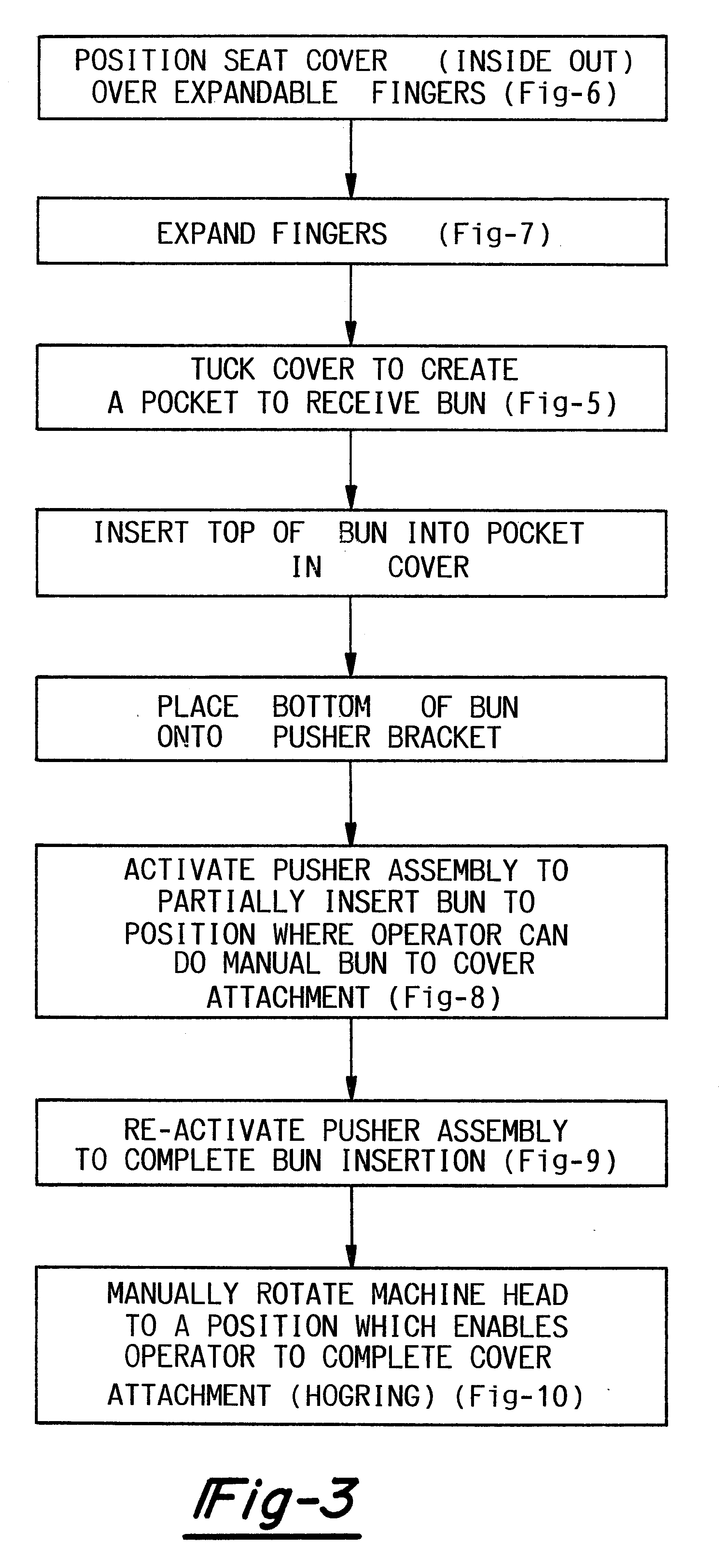
The blades are fitted with sensors that automatically expand the blade to their maximum positions according to the interior dimensions of the cover, but do not allow the blade to expand further, thus preventing tearing without the need for continuous adjustment by the operator.

Method used


Image

  • Method and apparatus for inserting an insert into a cover
  • Method and apparatus for inserting an insert into a cover
  • Method and apparatus for inserting an insert into a cover

Examples


Embodiment Construction

FIGS. 1 through 11 show the preferred embodiments of the present invention. While the configurations according to the illustrated embodiments are preferred, it is envisioned that alternate configurations of the present invention may be adopted without deviating from the invention as portrayed. The preferred embodiments are discussed hereafter.

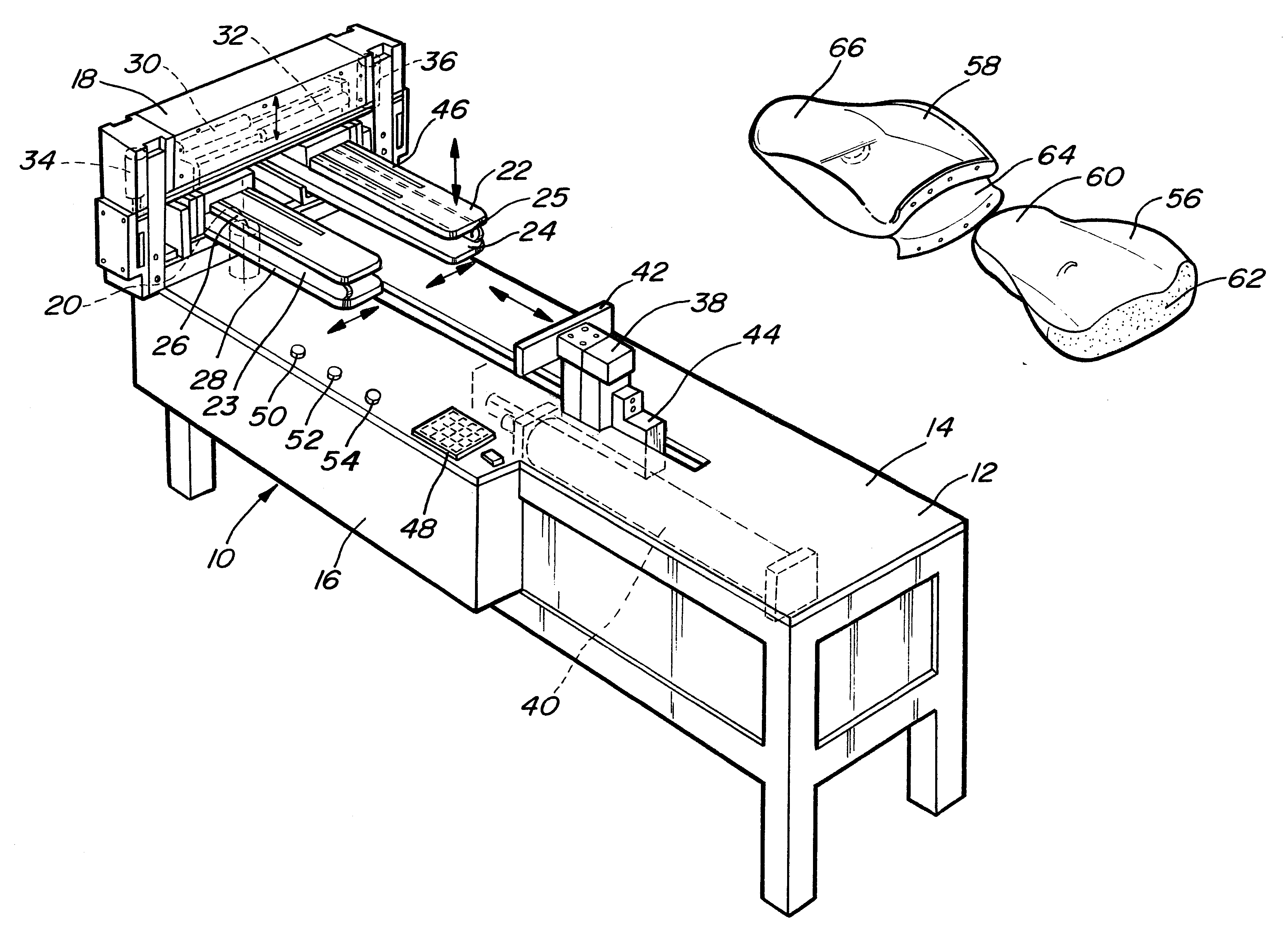
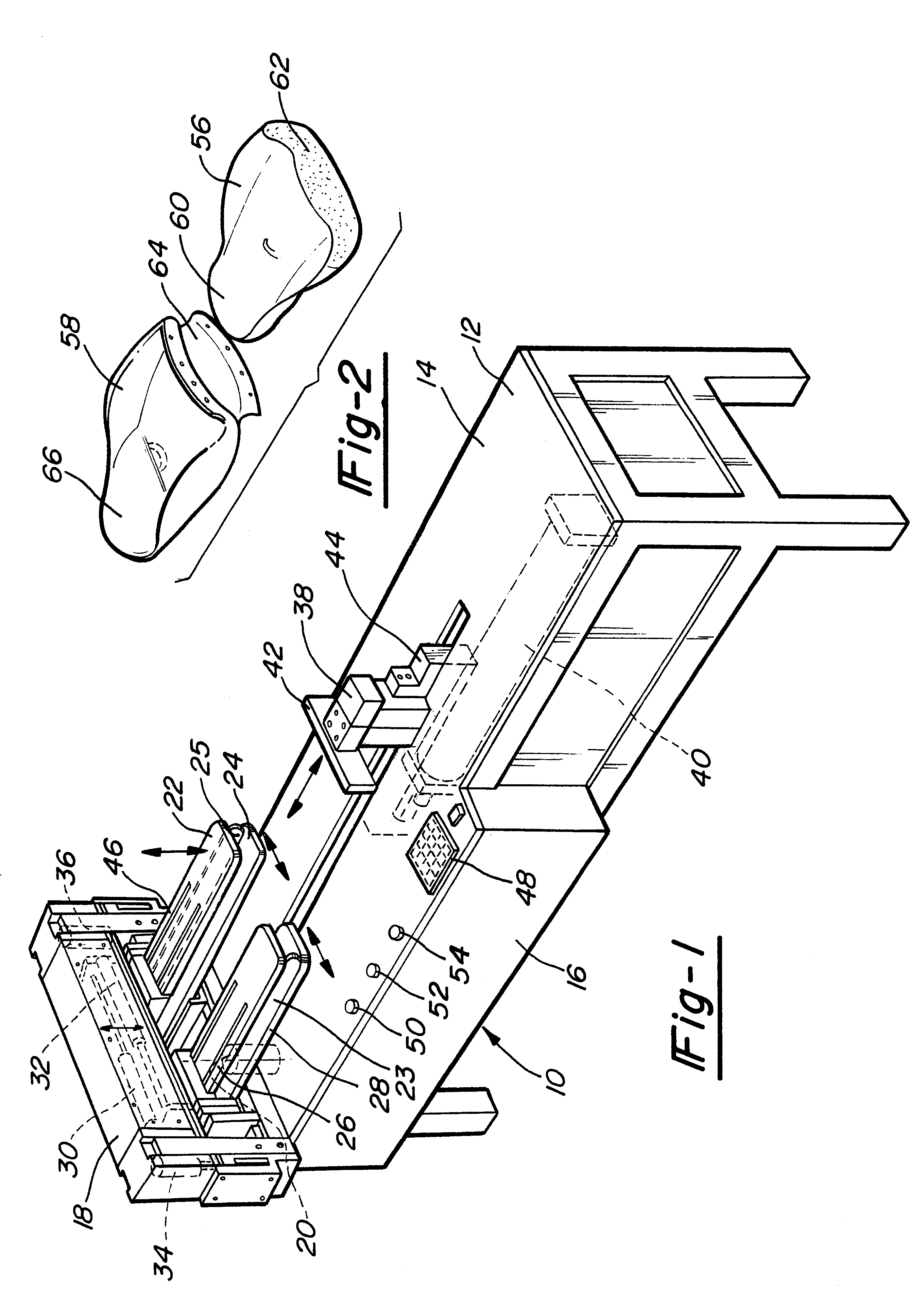
FIG. 1 is a perspective view of the preferred embodiment of the fitting apparatus of the present invention, generally indicated as 10. The apparatus 10 includes a bench 12 having an upper working surface 14 and a front 16.

A holding assembly 18 is illustrated on the working surface 14 at one end of the bench 12. The holding assembly 18 includes a body 19. Many components of the body are composed of extruded aluminum components. Preferably, the assembly 18 is pivotably mounted on the bench 12 by a pivoting arm 20. The pivoting arm 20 allows the operator to pivot the assembly from a cycling position, as illustrated, to an operator-accessible posit...


PUM

PropertyMeasurementUnit
Timeaaaaaaaaaa
Poweraaaaaaaaaa
Sizeaaaaaaaaaa

Abstract

A method and apparatus for inserting a supporting insert, such as a set insert (bun) for a vehicle, into a cover, such as a seat cover for a vehicle. The apparatus of the present invention includes a bench upon which a cover holding assembly and a stuffing bracket are provided. The holding assembly comprises four self-adjusting blades which are substantially grouped together at the beginning of the fitting cycle. After an inside-out seat cover's open end is fitted onto the blades, the blades move away from each other into the corners of the cover to expand the cover to its maximum size. The insert is then positioned between the top (closed) end of the covering material and the stuffing bracket. The stuffing bracket then drives the seat insert into the inside-out covering material, gradually turning the material outside-out as the insert is moved forward.

Description

I. FIELD OF THE INVENTIONThe present invention relates generally to a method and apparatus for inserting an insert into a cover. More particularly, the present invention relates to the stuffing of a cover, such as a vehicle seat cover, with an insert, such as a vehicle seat bun. The vehicle may be a car, a truck, a boat, or a plane. Other possible applications of the present invention are for use with home or office furniture. The apparatus comprises a bench having a material holding assembly and a movable stuffing bracket. The holding assembly comprises four self-adjusting blades that move to expand within the covering material prior to insertion of the bun.II. DESCRIPTION OF THE RELEVANT ARTConstruction and installation of interior components of vehicles is one of the more difficult and awkward stages of vehicle assembly. Interior fittings and accessories such as arm rests, head rests, visors, compartment covers as well as vehicle seat backs and bases are composed of an insert or ...

Claims


Application Information

Patent Timeline
IPC IPC(8): B68G7/05
CPCB68G7/051Y10T29/486
Inventor MINTZ, DAVIDMINTZ, NEILTREMBLAY, PIERRE
Owner MACHINE DESIGN SYST
Learn More