
Pre-tension and retention structure for composite fan blade

Active Publication Date: 2020-06-25
GENERAL ELECTRIC CO
View PDF10 Cites 1 Cited by
  • Summary
  • Abstract
  • Description
  • Claims
  • Application Information

AI Technical Summary

Benefits of technology

This patent describes a way to make blades stronger to prevent damage caused by failure. The solution is to add strings made of materials with greater strength than the blade's basic material. The strings can be made of materials like carbon fiber, steel, or shape memory alloys. This makes the blades less likely to break into pieces and cause damage.

Problems solved by technology

Such composite fan blades generally have a brittle failure characteristic such that a failure can occur under low strain relative to blades of other materials such as metal alloys.
However, during operation of the engine, a portion of a fan blade may contact the shroud and fail.
As a result, a blade may fracture or separate into multiple fragments.
The fragments can then cause more damage.
Thus one problem with conventional composite blades is that they are brittle and subject to separation into fragments, and when they do break into fragments, the fragments can loosely move about the engine and cause significant further damage.

Method used


Image

  • Pre-tension and retention structure for composite fan blade
  • Pre-tension and retention structure for composite fan blade
  • Pre-tension and retention structure for composite fan blade

Examples


Embodiment Construction

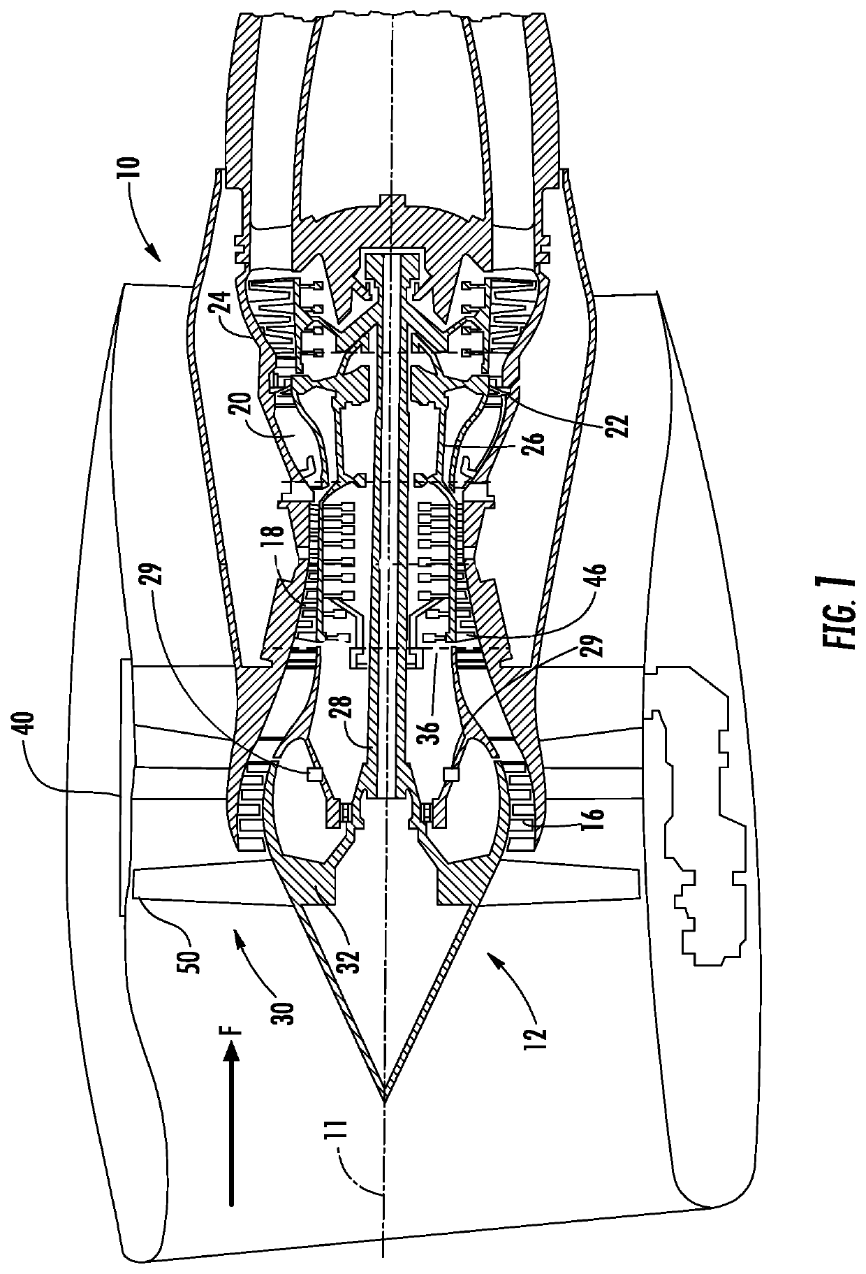
[0019]Referring to the drawings wherein identical reference numerals denote the same elements throughout the various views, FIG. 1 depicts an exemplary gas turbine engine 10 that includes a propulsion apparatus. While the illustrated example is a high-bypass turbofan engine, the principles of the present invention are also applicable to other types of engines, such as low-bypass turbofans, turbojets, turboprops, etc. The engine 10 has a longitudinal center line or axis 11.

[0020]It is noted that, as used herein, the terms “axial” and “longitudinal” both refer to a direction parallel to the centerline axis 11, while “radial” refers to a direction perpendicular to the axial direction, and “tangential” or “circumferential” refers to a direction mutually perpendicular to the axial and radial directions. As used herein, the terms “forward” or “front” refer to a location relatively upstream in an air flow passing through or around a component, and the terms “aft” or “rear” refer to a locat...


PUM

PropertyMeasurementUnit
Temperatureaaaaaaaaaa
Pressureaaaaaaaaaa
Distanceaaaaaaaaaa

Abstract

A blade for a propulsion apparatus that includes a body formed of a first material. The body includes opposed pressure and suction sides and extends in span between a root and a tip. The body extends in court between a leading edge and a trailing edge. A tension element is positioned within the body and extends between the root and the tip. The tension element includes at least one string that is configured to be under tension such that at least a portion of the blade between the root and the tip is under compression.

Description

BACKGROUND OF THE INVENTION[0001]This invention relates to turbofan blades formed of composite material and structures for strengthening and reinforcing such composite blades.[0002]A typical composite fan blade includes reinforcing fibers embedded in a matrix (e.g. carbon fibers in epoxy). Such composite fan blades generally have a brittle failure characteristic such that a failure can occur under low strain relative to blades of other materials such as metal alloys.[0003]A gas turbine engine includes a turbomachinery core having a high-pressure compressor, a combustor, and a high-pressure turbine in a serial flow relationship. The core is operable in a known manner to generate a primary flow of propulsive gas. A typical turbofan engine adds a low-pressure turbine driven by the core exhaust gases which in turn drives a fan rotor through a shaft to generate a bypass flow of propulsive gas. In the case of a high bypass engine this provides the majority of the total engine thrust.[0004...

Claims


Application Information

Patent Timeline
IPC IPC(8): F01D5/28F04D29/38
CPCF01D5/18F01D5/282F04D29/388F01D5/147F04D29/324F05D2300/614B64C11/24F04D29/023F02C3/04F05D2300/603Y02T50/60
Inventor GANIGER, RAVINDRA SHANKARSAKALA, VISWANADHA GUPTAKRAY, NICHOLAS JOSEPH
Owner GENERAL ELECTRIC CO
Learn More