Reduced weight pneumatic tires

Inactive Publication Date: 2001-07-17
BRIDGESTONE CORP
View PDF8 Cites 12 Cited by
  • Summary
  • Abstract
  • Description
  • Claims
  • Application Information

AI Technical Summary

Problems solved by technology

However, steel cord is very heavy in the weight per unit length as compared with the other tire cords (rayon cord, nylon cord,

Method used


Image

  • Reduced weight pneumatic tires
  • Reduced weight pneumatic tires
  • Reduced weight pneumatic tires

Examples


example

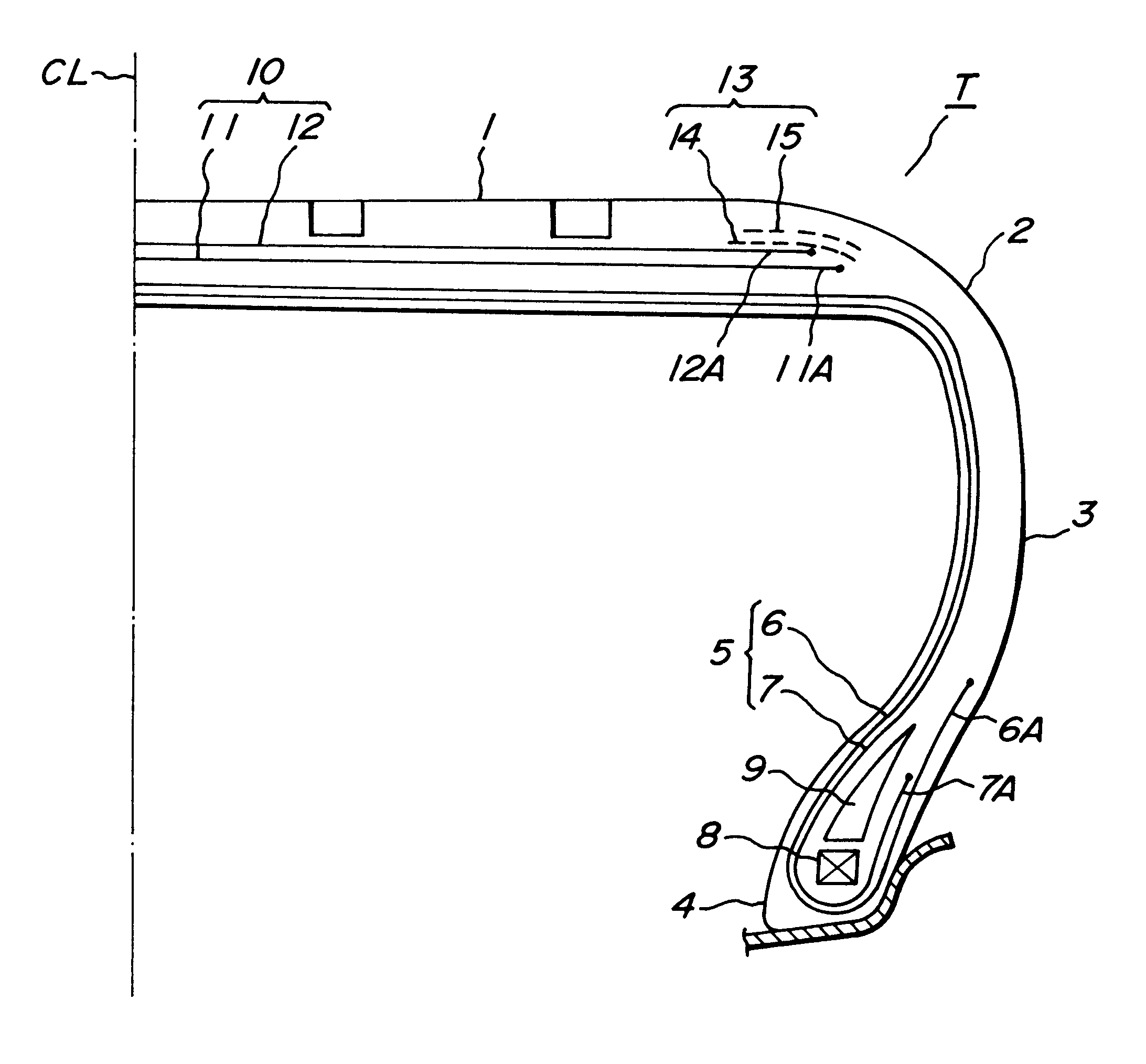
There are provided a Comparative Tire, Invention Tires 1 and 2 and a conventional tire each having a tire size of 225 / 50R16. In each of these tires, structures of the carcass and belt are shown in Table 1. With respect to each of these tires, maximum values of CF produced in left turning (occurrence of left SA) and right turning (occurrence of right SA) are measured by means of a CF measuring test machine. And also, each of these tires is run at a high speed on a drum testing machine to measure a running distance until the tire is broken, whereby the high-speed durability is evaluated. The measured values are represented by an index on the basis that the comparative tire is 100 and also shown in Table 1.

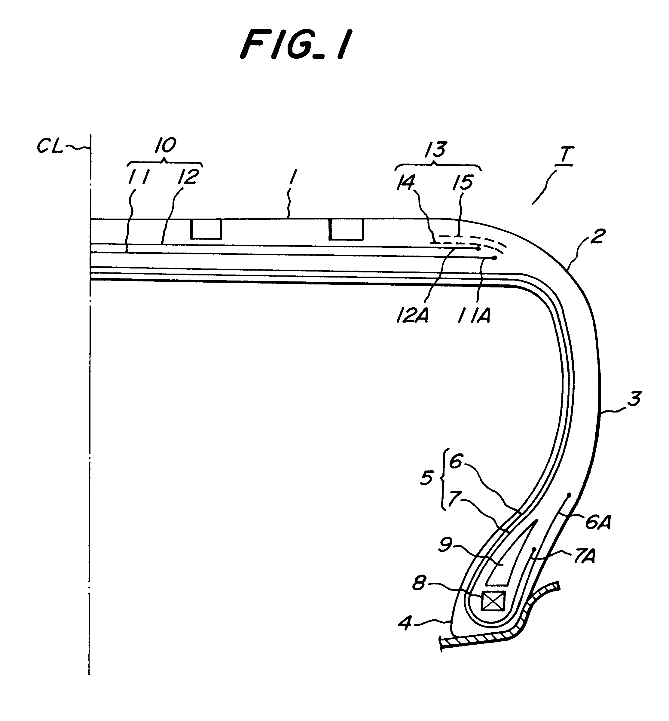
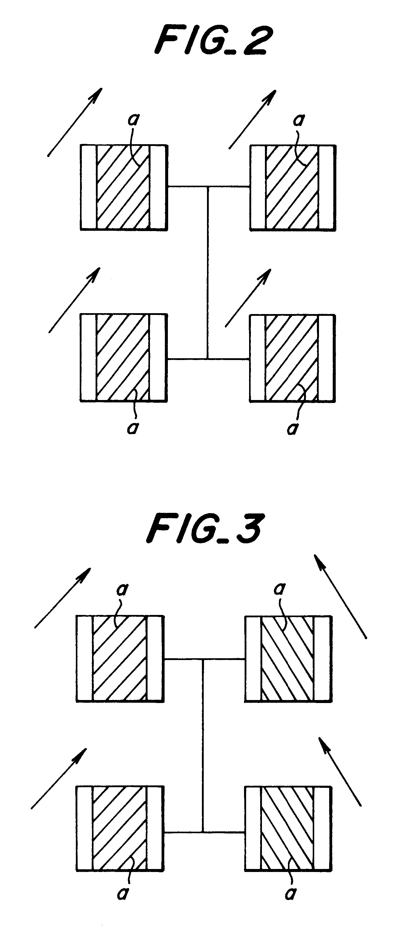
Then, each of the Comparative Tire and the Invention Tires 1 and 2 is mounted onto a test vehicle to evaluate the steering stability in the cornering and the cornering characteristic. Moreover, the mounting method of the tire is shown in Table 2. The Mounting Examples 1-4 are accordi...


PUM

PropertyMeasurementUnit
Angleaaaaaaaaaa
Angleaaaaaaaaaa
Angleaaaaaaaaaa

Abstract

A pneumatic tire comprises at least one carcass ply of textile cords and a belt comprised of two cross belt layers containing textile cords arranged at a cord inclination angle of 10-45° with respect to the equatorial plane, in which a difference of cord inclination angle between the two cross belt layers with respect to the equatorial plane of the tire is within a range of 5-35° in the widthwise direction, and is mounted onto at least either left-side or right-side front wheel of a four-wheeled vehicle.

Description

1. Field of the InventionThis invention relates to a pneumatic tire usable for high-performance type passenger car and racing car and a method of mounting the same on a vehicle.2. Description of Related ArtIn the conventional pneumatic tire used in the high-performance type passenger car, it has generally been attempted to improve the high-speed durability and steering stability by adopting high-rigidity and high-strength steel cords (tensile modulus: about 15000-20000 kgf / mm.sup.2) in a belt layer to thereby enhance the rigidity of the belt layer.However, steel cord is very heavy in the weight per unit length as compared with the other tire cords (rayon cord, nylon cord, polyester cord and the like), so that the tire weight is undesirably increased by adopting the steel cords in the belt layer. The increase of the tire weight is not related to fuel consumption.It is, therefore, an object of the invention to provide a pneumatic tire capable of establishing the high-speed durability ...

Claims


Application Information

Patent Timeline
IPC IPC(8): B60C9/20B60C19/00B60C9/00B60C9/06B60C5/00B60C9/08B60C9/18
CPCB60C9/2009B60C19/001Y10T152/10792Y10T152/10765
Inventor UBUKATA, TORUHAMAMURA, KAZUYUKI
Owner BRIDGESTONE CORP
Why Eureka
Try Eureka