Driving force control system for vehicle

a technology of driving force and control system, which is applied in the direction of control devices, driver input parameters, vehicle components, etc., can solve the problems of deterioration of wheels, torque may not be controlled properly, and deterioration of drive feeling, so as to improve driving comfort, simplify the structure of the control system, and improve the cornering performance of the vehicl

Active Publication Date: 2015-11-10
TOYOTA JIDOSHA KK
View PDF14 Cites 3 Cited by
  • Summary
  • Abstract
  • Description
  • Claims
  • Application Information

AI Technical Summary

Benefits of technology

[0008]In order to solve the foregoing technical problems, it is an object of this invention to provide a system for controlling a stability factor to control a driving force in a manner to improve a cornering performance of the vehicle.
[0016]Thus, according to the present invention, a travelling condition in which the change rate of the steering angle is smaller than the reference value, more specifically, a travelling condition in which the steering angle is not being changed significantly so that the vehicle is travelling in a substantially straight line or along an arc with a constant turning radius is used as the reference condition, and the actual value is corrected to conform to the target value under the reference condition. Specifically, the correction value is calculated based on a comparison result between the current actual value and the target value, and the driving force is corrected based on the correction value. Consequently, when the vehicle is travelling in a straight line or along an arc with a constant turning radius, the corrected value of the detection value of the sensor and the actual stability factor calculated based on the detection value conform to the target value. In this situation, therefore, a correction of the driving force will not be carried out. In contrast, if the steering angle is being changed, the detection value of the sensor and the actual value of the stability factor are corrected, and the driving force is corrected in accordance therewith. As a result, when the steering angle is being changed so that the vehicle is yawing, the driving force is corrected in a manner such that the turning condition of the vehicle, that is, the stability factor is approximated to the target value. According to the present invention, therefore, a cornering performance of the vehicle is improved. However, the driving force will not be corrected when the vehicle is travelling in a straight line or along an arc with a constant turning radius. That is, the driving force is corrected only when the steering angle is changed. Therefore, the driver will not feel any unintentional change in the driving force so that the driving comfort is improved.
[0017]As described, according to the present invention, the travelling condition in which the steering angle is not being changed significantly so that the vehicle is travelling in a substantially straight line or along an arc with a constant turning radius is the reference condition to carry out the correction. Therefore, it is not necessary to correct the zero point of the sensor such as the yaw rate sensor. That is an additional sensor for detecting an orientation and a position of the vehicle is not required. For this reason, a structure of the control system can be simplified.

Problems solved by technology

However, cornering powers of front and rear wheels may be changed depending on loads applied to the front and rear wheels, deterioration of the wheels with age and so on.
However, if the detection value of the sensor has an accidental error, the stability factor will not represent the actual vehicle behavior.
In this case, therefore, the torque may not be controlled properly to deteriorate a drive feeling.
However, according to the teachings of Japanese Patent Laid-Open No. 2008-275344, another sensor such as a radar is required to detect a turning condition of the vehicle in addition to the yaw rate sensor, and this complicates a structure of the device and enlarges the device.

Method used


Image

  • Driving force control system for vehicle
  • Driving force control system for vehicle
  • Driving force control system for vehicle

Examples


Embodiment Construction

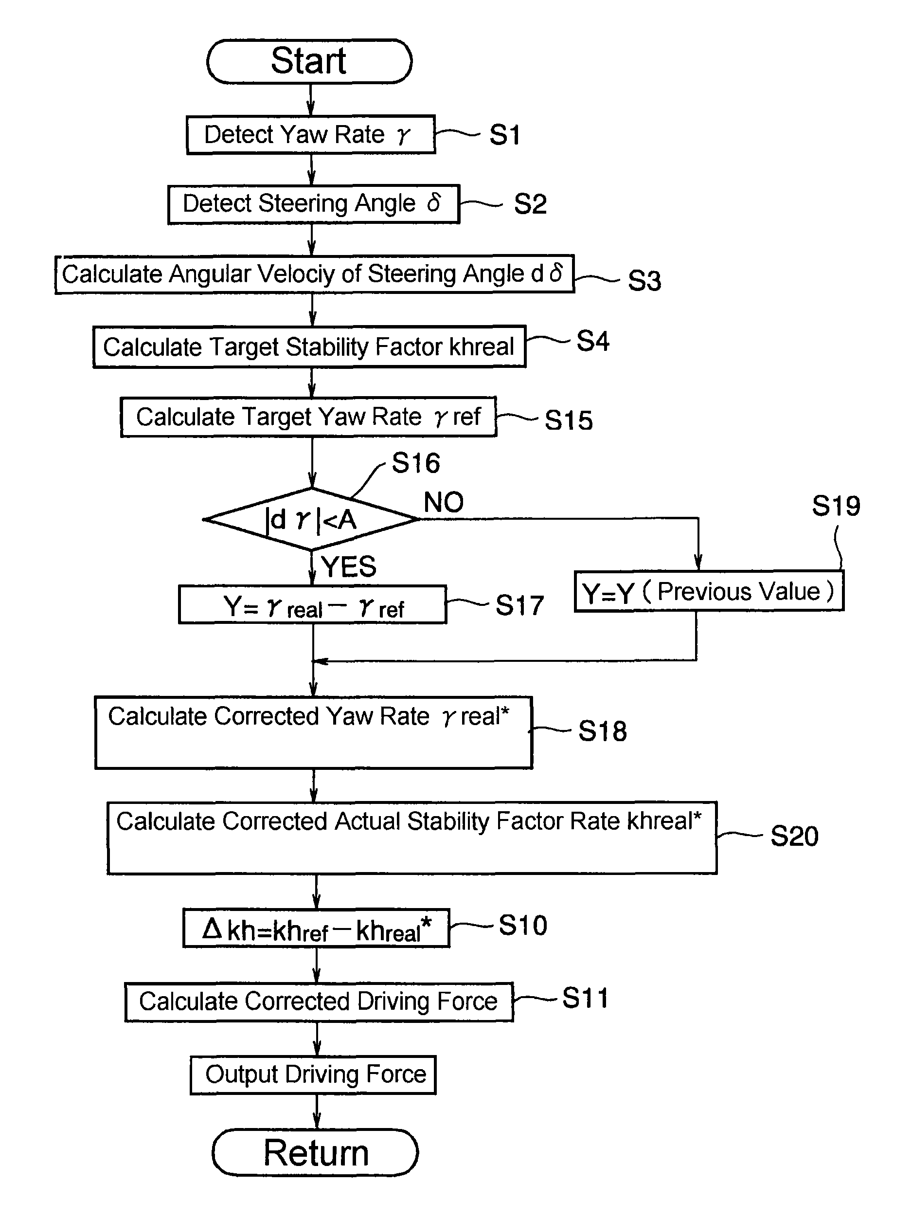
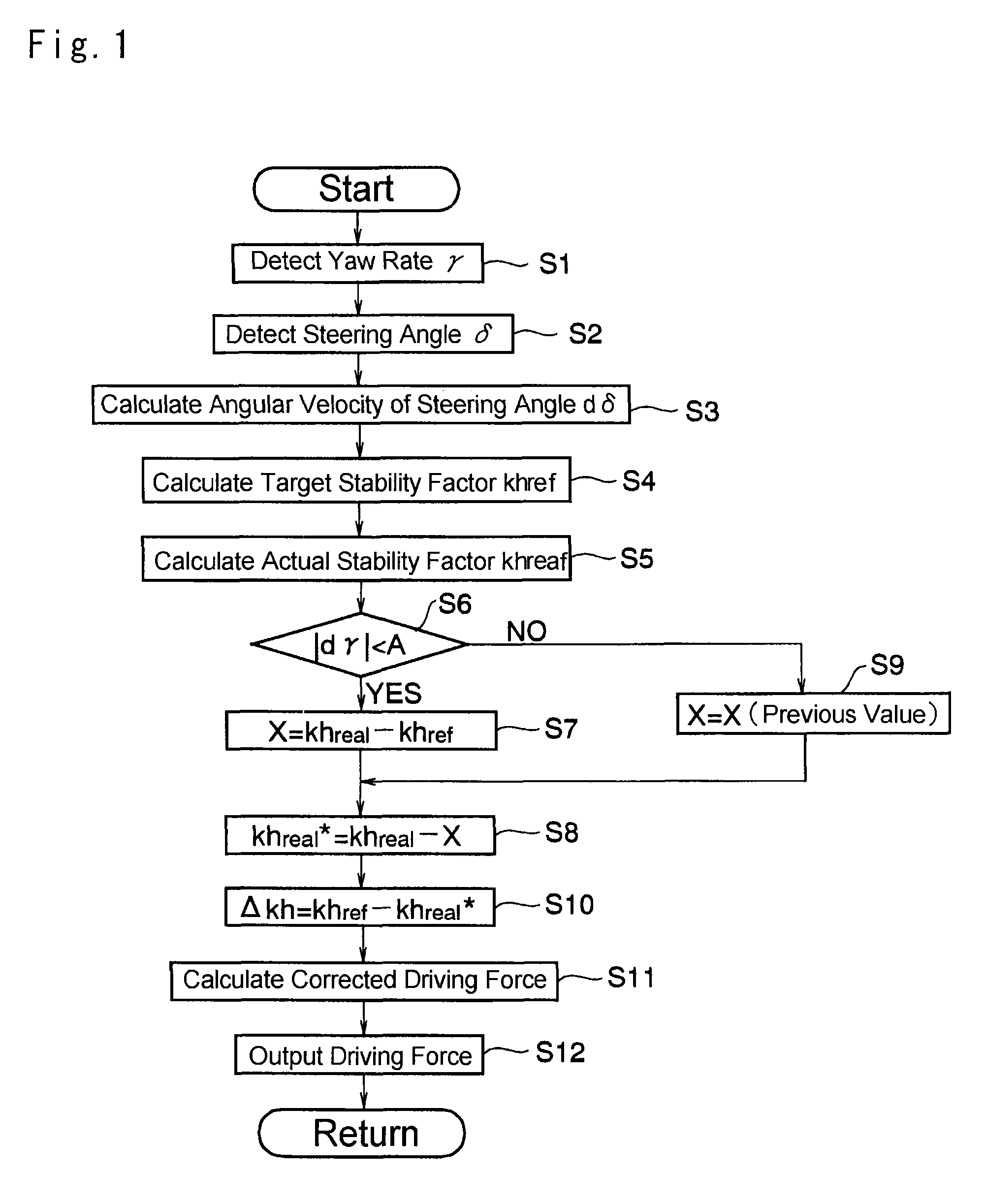
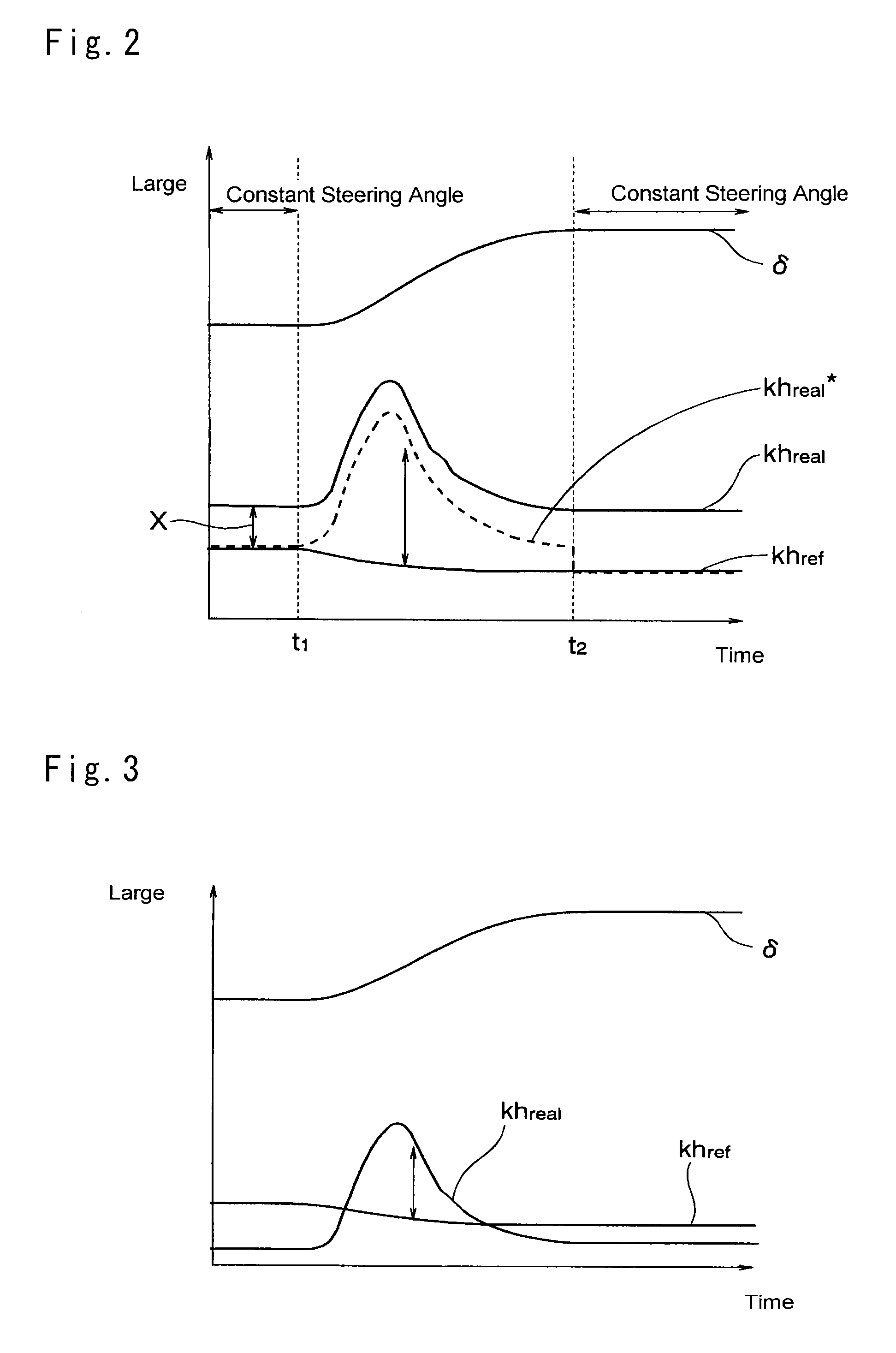
[0025]The present invention relates generally to a system for controlling a driving force to improve a cornering performance of the vehicle. More specifically, the present invention relates to a system for controlling a driving force in a manner to conform the stability factor obtained based on a detection value of a sensor to a predetermined target value. However, a zero point of the sensor may be varied due to a change in temperature or as time advances. In this case, accuracy of a detection value of the sensor may be degraded to represent the actual condition of the vehicle. Consequently, the actual stability factor may be diverged from the actual condition of the vehicle. In order to correct such error or divergence to conform the stability factor to the target value as close as possible, the driving force control system of the present invention is configured to correct the driving force.

[0026]The present invention is applied to a vehicle in which the driving force can be contro...


PUM


Abstract

A driving force control system for a vehicle, which is configured to control a driving force of a vehicle by calculating an actual value of a stability factor of a running vehicle based on a detection value of a predetermined sensor, and adjusting the calculated actual value of the stability factor toward a target value of the stability factor determined depending on a travelling condition of the vehicle. The driving force control system is comprised of: a steering judging unit that judges a fact that a change rate of a steering angle of the vehicle is smaller than a predetermined reference value; a correction value calculating unit that corrects the actual value of the stability factor based on a comparison between an actual value and a target value of a physical amount with respect to a turning motion of the vehicle, in case the steering judging unit judges that the change rate of the steering angle is smaller than a reference value; and a driving force correcting unit that corrects the driving force based on the correction value.

Description

TECHNICAL FIELD[0001]This invention relates to a system for controlling a vehicle behavior such as a cornering performance, and especially to a system for controlling a driving force in a manner to correct a stability factor having a significant effect on the vehicle behavior to achieve a target stability factor.BACKGROUND ART[0002]A stability factor is one of the significant factors affecting the vehicle behavior. Provided that the vehicle is turning steadily without accelerating and decelerating, the stability factor can be expressed using an inertial mass, a wheel base, cornering powers (i.e., cornering forces) of front and rear wheels, a distance between a gravity center of the vehicle and a front axle, a distance between the gravity center of the vehicle and a rear axle and etc. Otherwise, the stability factor can be obtained based on an actual steering angle, a wheel base, a lateral acceleration and a vehicle speed. Such formula may be modified to calculate the stability facto...

Claims


Application Information

Patent Timeline
Patent Type & Authority Patents(United States)
IPC IPC(8): B60W30/045B60W30/02
CPCB60W30/045B60W30/02B60W30/025B60W2520/14B60W2540/18B60W40/114B60W50/029B60T8/1755B60W2050/0215B60T2201/16B60T2270/303
Inventor OKUMURA, KAZUYASHIMURA, SOUICHIROU
Owner TOYOTA JIDOSHA KK
Why Eureka
Try Eureka