
Method for the detection of the relative depth of objects in an image from a pair of images

a technology of image and relative depth, applied in image data processing, television systems, instruments, etc., can solve the problems of insufficient segmentation information to deduce, additional delay in analysis, and lack of precision

Inactive Publication Date: 2001-07-17
HANGER SOLUTIONS LLC
View PDF1 Cites 27 Cited by
  • Summary
  • Abstract
  • Description
  • Claims
  • Application Information

AI Technical Summary

Problems solved by technology

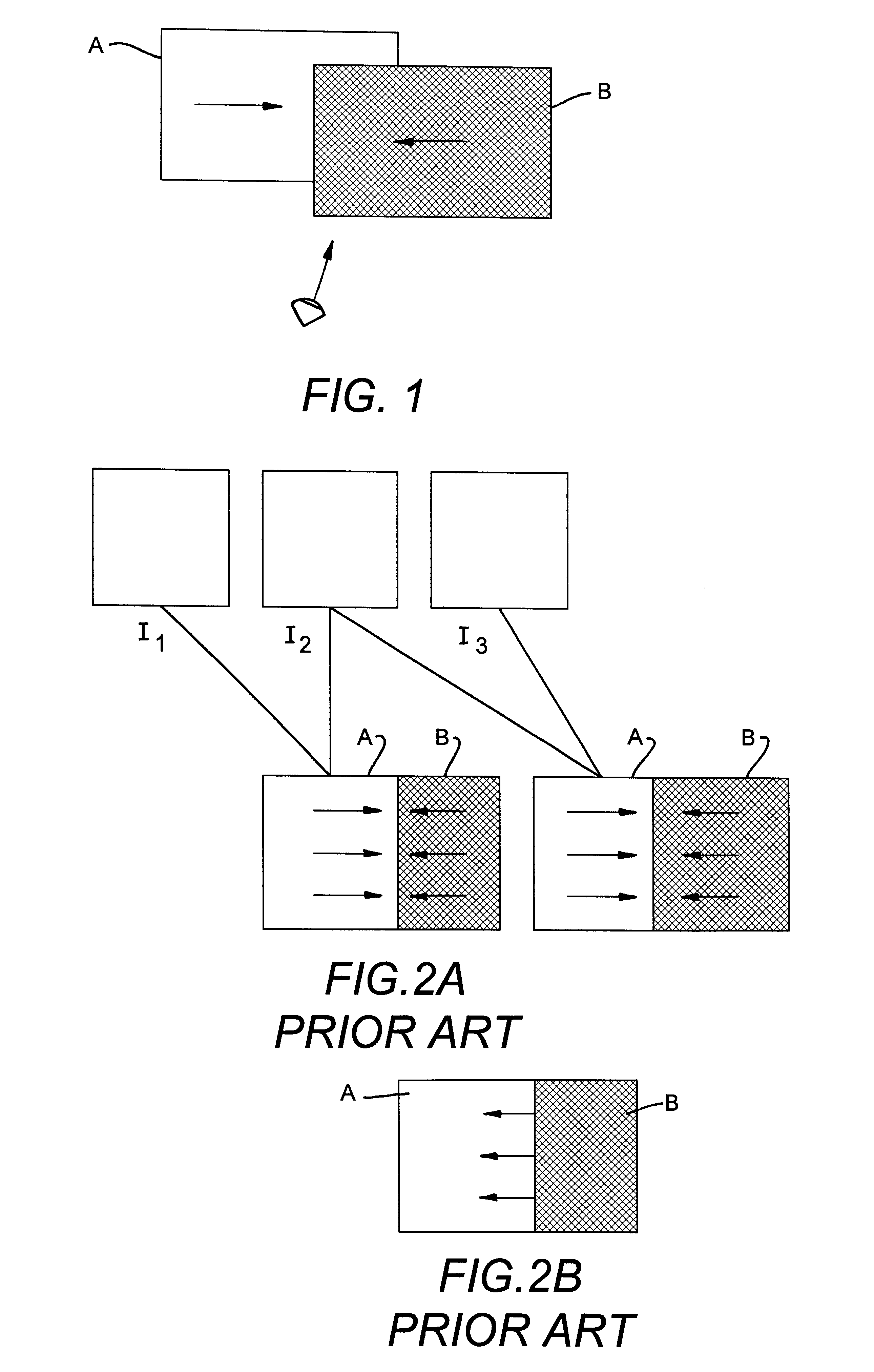
This motion segmentation does not contain sufficient information to deduce the relative depth of the two objects.
These techniques use three images (two motion segmentations) to determine the motion of the contours; the problems of lack of precision in the localizing of the boundaries spread over into the estimation of the motion of the contours and therefore in the detection of the depth.
Furthermore, this leads to an additional delay in analysis.
Furthermore, the field of application of these techniques is restricted to cases where the motion is relatively great.

Method used


Image

  • Method for the detection of the relative depth of objects in an image from a pair of images
  • Method for the detection of the relative depth of objects in an image from a pair of images
  • Method for the detection of the relative depth of objects in an image from a pair of images

Examples


Embodiment Construction

The method according to the invention can be implemented by means of a program loaded into a microcomputer in order to implement the different steps that shall be described hereinafter or by means of an electronic device designed for this purpose.

The microcomputer (not shown) could be connected to one or two cameras making it possible to obtain two different shots of the scene U, W that are used as input data in the processing sequence that follows and take the form of matrices of pixels after digitization.

It is of course possible instead to have audiovisual equipment with a processing unit and pre-recorded images.

For a clearer understanding of the rest of the invention, reference will be made to FIGS. 3A-3C and 4 and 5A, 5B.

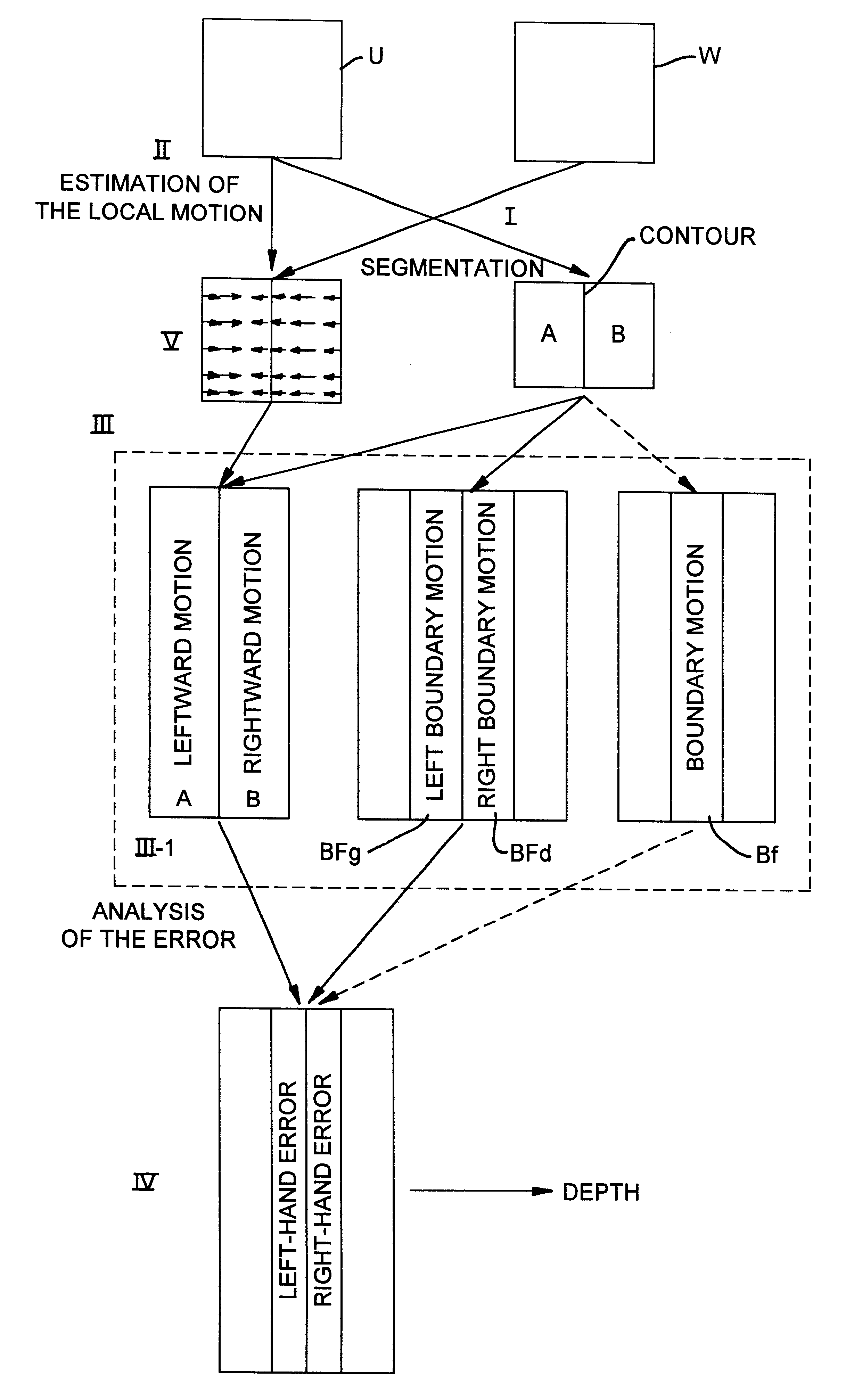
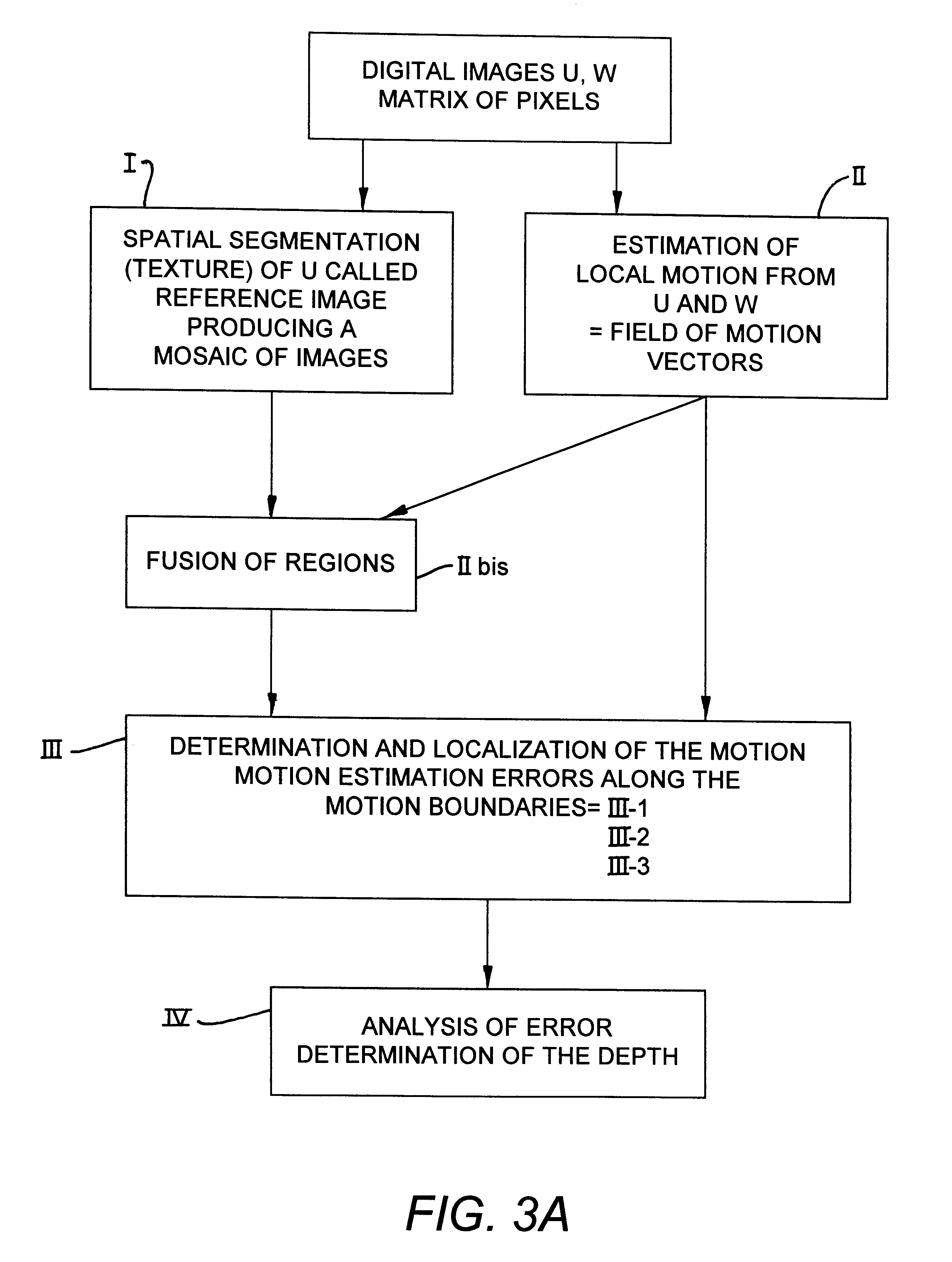
FIG. 3A illustrates the sequence of processing operations.

This sequence has two parallel processing sets, of which one I enables the obtaining of a spatial segmentation of one of the images, for example the image U, which shall hereinafter be considered to be th...


PUM


Abstract

Disclosed is a method for the detection of the relative depth of two neighboring regions in relative motion with respect to each other in two images obtained from different shots of a scene, in order to know the composition of the scene. The method consists in carrying out a spatial segmentation of one of the images, called a reference image; a local estimation of the motion between the two images, the resultant vector field of which is called local motion; a determining of the motion estimation errors along the motion boundaries; and an analysis of the localization of the motion estimation errors along the motion boundaries to conclude that a region A is in front of a region B when the motion estimation error along the boundary is chiefly localized on the side B of this boundary.

Description

1. Field of the InventionThe invention relates to a method for the detection of the relative depth of objects in an image from a pair of images.The general context of the invention is the estimation of the relative depths of objects seen in images coming from different shots whether these images are taken successively in time or from different angles.This method is part of the framework of various applications requiring a semantic analysis of image sequences. In particular, in the field of multimedia, the growing quantity of audiovisual data is creating the need for new functions such as the interactivity and the integration of objects of different kinds. The new MPEG-4 standard makes it possible to show a scene as a composition of objects but it does not specify the way in which the scene is analyzed.2. Description of the Prior ArtThe current techniques relevant to the framework of this invention study the zones of occlusion that appear in a sequence of images. These techniques are...

Claims


Application Information

Patent Timeline
IPC IPC(8): G06T7/00H04N7/32G06T1/00H04N13/00
CPCG06T7/0075G06T7/0022G06T7/97G06T7/593
Inventor AVARO, OLIVIERBERGEN, LOTHARMEYER, FERNAND
Owner HANGER SOLUTIONS LLC
Learn More