Hand-held power working machine

a hand-held power and working machine technology, applied in the field of hand-held power working machines, can solve the problems of troublesome manufacturing, clipper blades to be employed in the aforementioned hand-held power working machine are not interchangeable with other types of clipper blades,

Inactive Publication Date: 2001-07-24
KIORITZ
View PDF9 Cites 65 Cited by
  • Summary
  • Abstract
  • Description
  • Claims
  • Application Information

AI Technical Summary

Problems solved by technology

This design also involves a troublesome working during manufacture.
Namely, there is an inconvenience in that the clipper blades to b

Method used


Image

  • Hand-held power working machine
  • Hand-held power working machine
  • Hand-held power working machine

Examples


Embodiment Construction

Next, a hand-held power working machine representing one embodiment of the invention will be explained with reference to the drawings. It will be understood, however, that the invention should not be construed to be limited by this embodiment, but may be variously modified within the spirit and scope of the invention as defined in the appended claims.

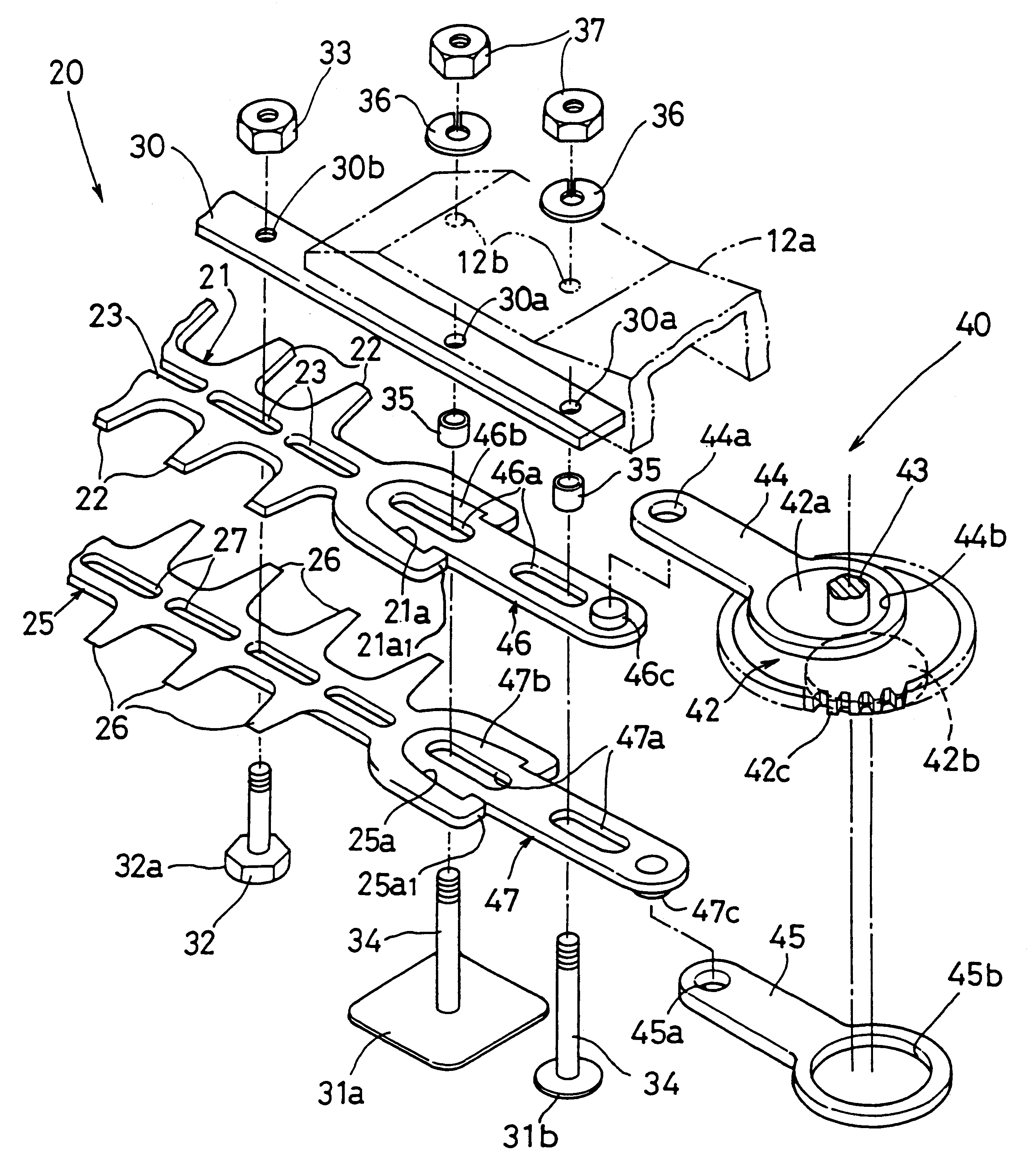
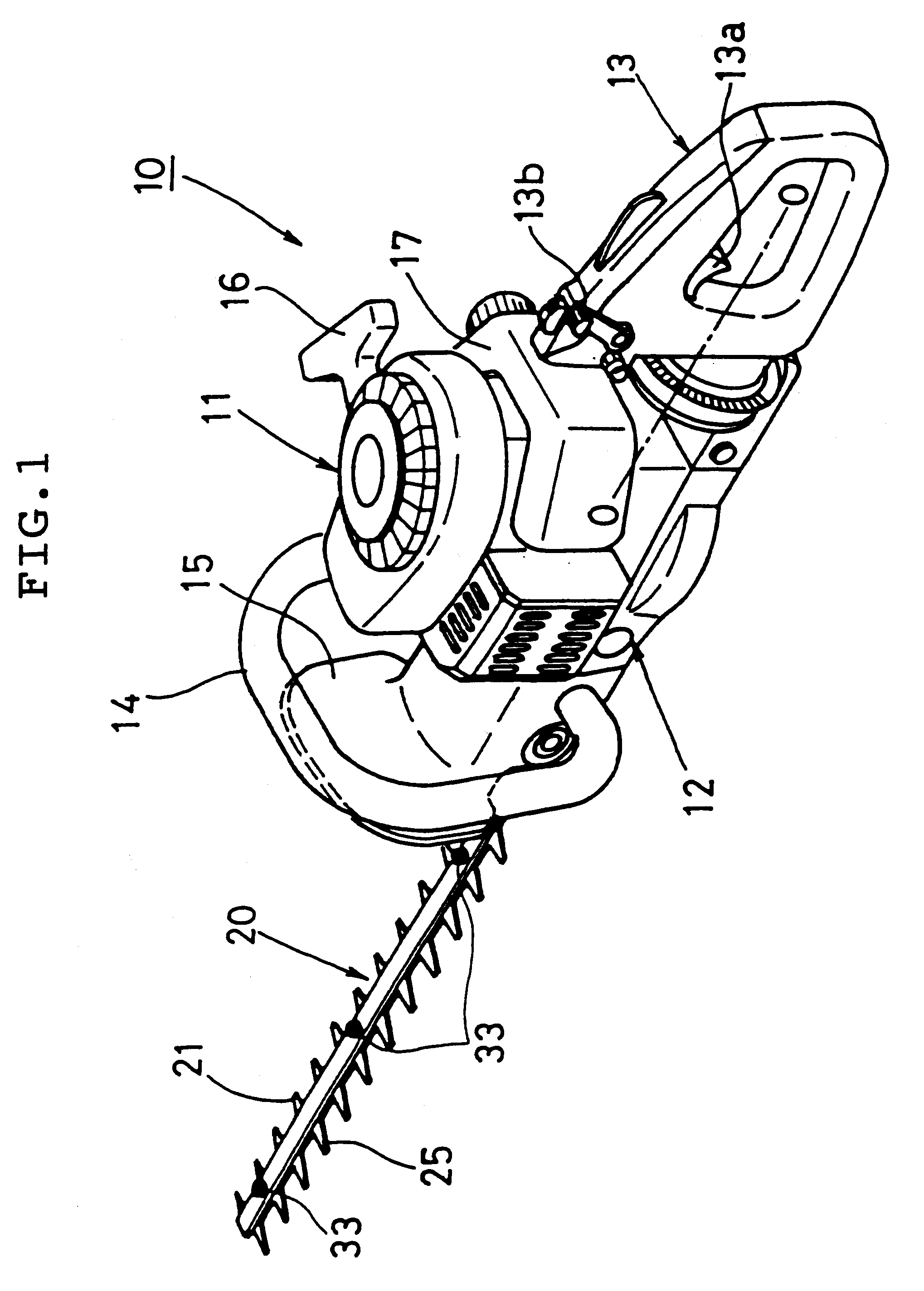
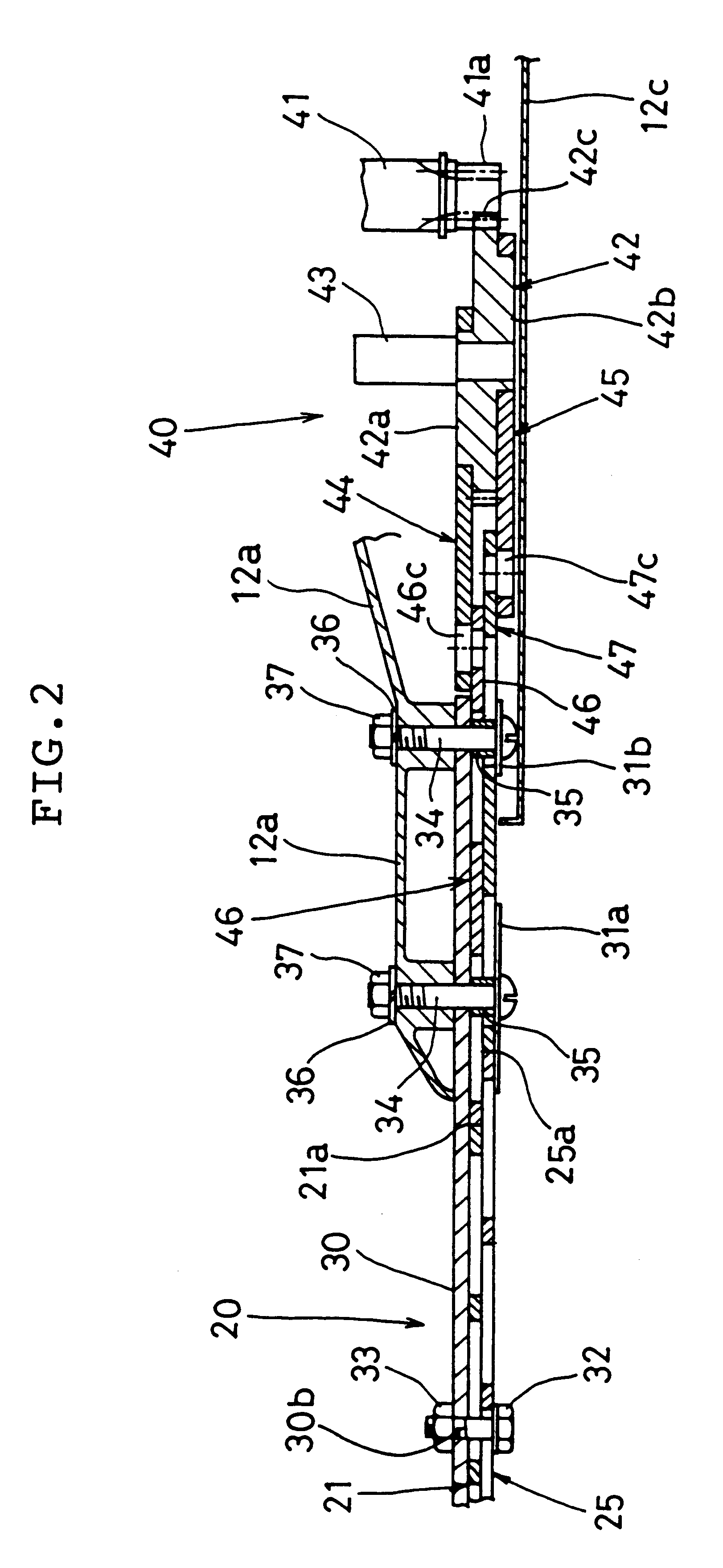
FIG. 1 is a perspective view illustrating one embodiment of a hedge trimmer 10 provided with a clipper blades-mounted working portion 20 according to this embodiment. The hedge trimmer 10 comprises an air-cooled two-stroke gasoline internal combustion engine 11, a mount base portion 12 enclosing a lower portion of the main body 12a (see FIG. 2) of the machine 10 which is integrally formed with a transmission case housing a power transmission device 40 (to be explained hereinafter), such as gears, to be actuated by the internal combustion engine 11. The clipper blades-mounted working portion 20 comprises a pair of upper and lower clipper...


PUM


Abstract

A hand-held power working machine in which the clipper blades thereof can be easily dismounted for the exchange or grinding thereof in a way that minimizes the possibility of damage to the power transmission device or the clipper blades in the course of such dismounting. Also, conventional integrated type clipper blades can be mounted thereon. The power working machine includes a working portion provided with a pair of clipper blades and a power transmission device for transmitting a reciprocating driving power to the working portion, wherein the power transmission device includes a pair of intermediate reciprocating driving plates which are couplingly interposed between a pair of reciprocating movement-guiding arms, to be driven by a driving rotor, and the pair of clipper blades.

Description

1. Field of the InventionThis invention relates to a hand-held power working machine, and in particular to a power transmission device for a working member and to the clipper blades (saw blades), which are designed to be disposed at the front portion of a power working machine such as a hedge trimmer.2. The Prior ArtA hand-held power working machine, such as a hedge trimmer, is generally constituted by a prime mover case housing a prime mover, such as an internal combustion engine, a mount base portion supporting a transmission case housing a power transmission device, such as gears, to be actuated by the prime mover, a working portion comprising clipper blades to be actuated via the aforementioned power transmission device by the prime mover, and a handling portion attached to the prime mover case, the transmission case or the mount base portion. The handling portion is constituted, for the convenience of manipulation thereof, by a front handle portion and a rear handle portion. Fo...

Claims


Application Information

Patent Timeline
IPC IPC(8): A01G3/00A01G3/053A01G3/04
CPCA01G3/053
Inventor NAGASHIMA, AKIRA
Owner KIORITZ
Why Eureka
Try Eureka