Boot arrangement for a constant velocity joint

a constant velocity joint and boot arrangement technology, applied in the direction of yielding couplings, shafts and bearings, engine seals, etc., can solve the problems of unsatisfactory stress on the boot, high speed centrifugal ballooning, and the boot is also vulnerable to wear and tear, so as to achieve significant reduction or elimination of the axial deformation of the boot, and effectively inhibit contact

Inactive Publication Date: 2001-07-24
GKN AUTOMOTIVE INC
View PDF3 Cites 60 Cited by
  • Summary
  • Abstract
  • Description
  • Claims
  • Application Information

AI Technical Summary

Benefits of technology

The present invention addresses the shortcomings of the prior art by providing a boot arrangement including a sleeve that is moveable along a shaft, and a boot that is connected to the sleeve a

Problems solved by technology

This axial deformation of the boot causes undesirable stress on the boot.
With such a configuration, the boot is also vulnerable to centrifugal balloonin

Method used


Image

  • Boot arrangement for a constant velocity joint
  • Boot arrangement for a constant velocity joint
  • Boot arrangement for a constant velocity joint

Examples


Embodiment Construction

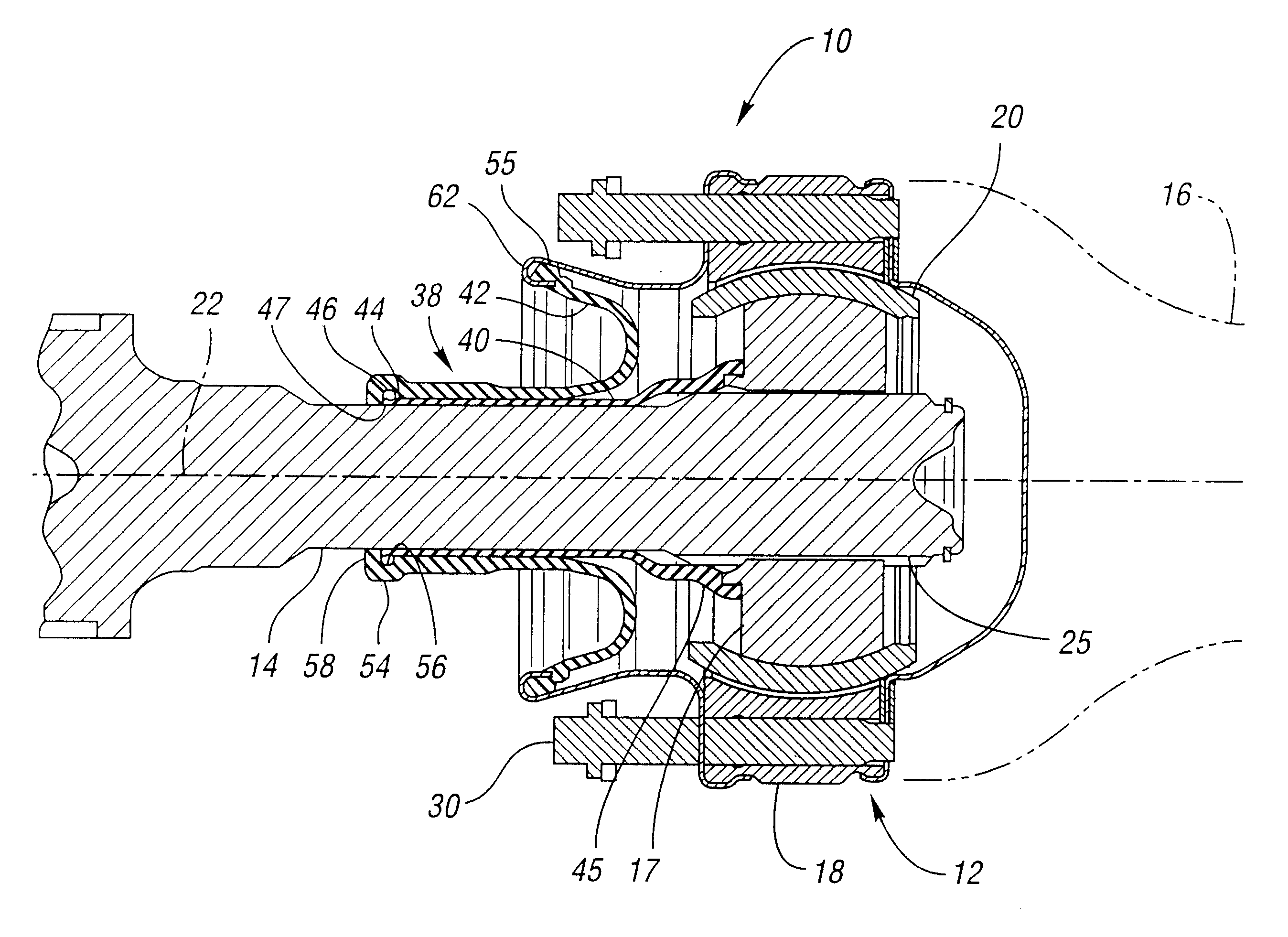
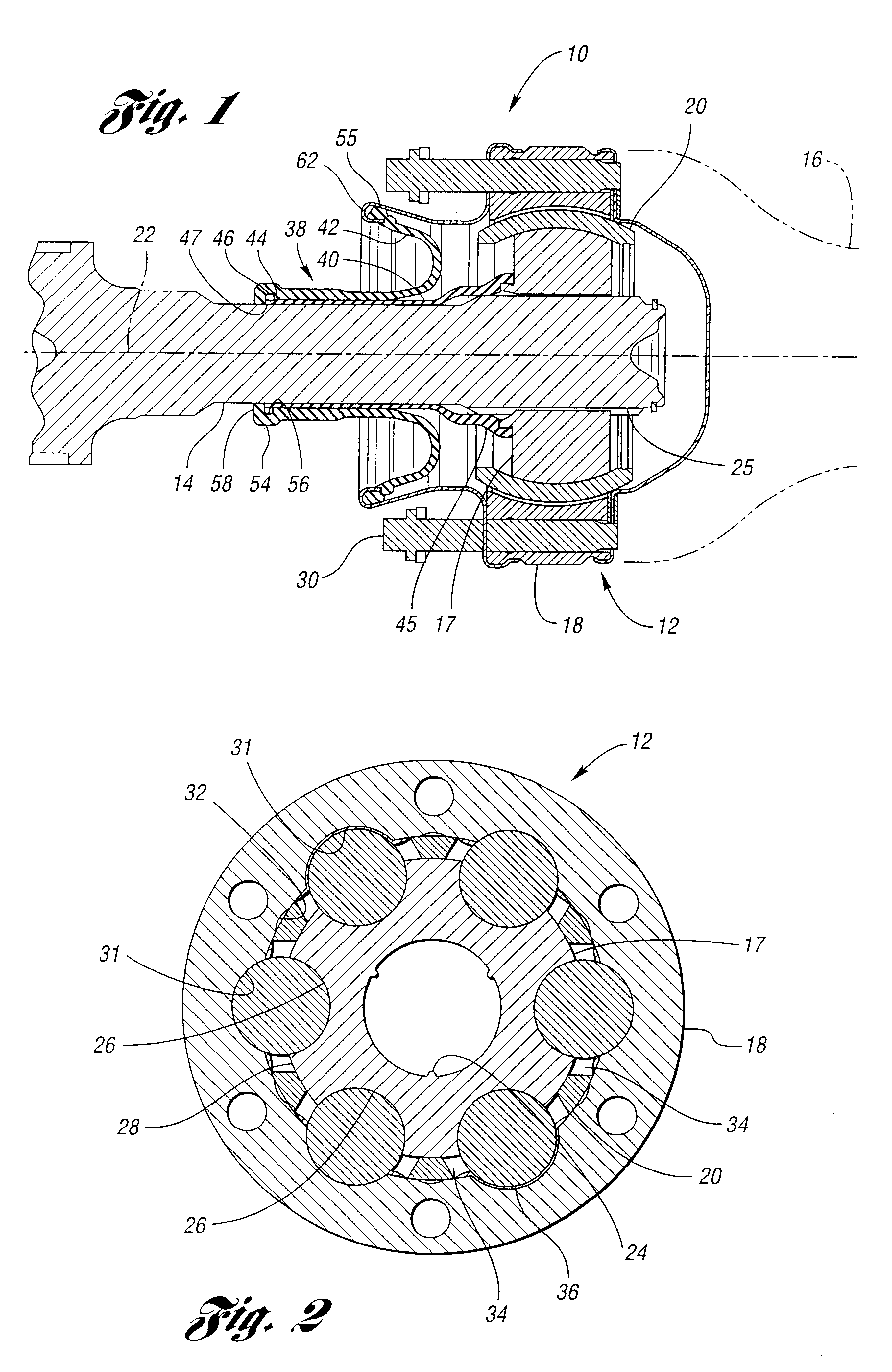
FIG. 1 shows a constant velocity joint and shaft assembly 10 according to the invention. The assembly 10 includes a constant velocity joint 12 for transmitting torque between a first shaft 14 and another component such as a second shaft 16. One of the shafts 14 or 16 may be a drive shaft such as a propeller shaft, and the other shaft 14 or 16 may be a driven shaft such as a half shaft. The joint 12 includes a first joint part such as an inner race 17, a second joint part such as an outer race 18, and a ball cage 20 disposed in an annular space between the races 17 and 18. While the joint 12 is configured to operate through a wide range of angles, FIG. 1 shows the races 17 and 18 and ball cage 20 aligned along a common central axis 22.

Referring to FIGS. 1 through 3, the inner race 17 is slidably connected to the first shaft 14 in any suitable manner. For example, the inner race 17 may be provided with a splined opening 24 that mates with a splined outer surface 25 of the first shaft ...


PUM


Abstract

A boot arrangement is provided for use with a constant velocity joint and shaft assembly including a shaft, a first joint part slidably engageable with the shaft, and a second joint part cooperable with the first joint part to transmit torque therebetween. The boot arrangement includes a sleeve adapted to slidably engage the shaft and having first and second ends. The second end of the sleeve is adapted to be connected to the first joint part. The arrangement further includes a boot having a first end adapted to be connected to the sleeve proximate the first end of the sleeve, and a second end adapted to be operatively connected to the second joint part.

Description

The invention relates to a boot arrangement for a constant velocity joint and shaft assembly.A constant velocity joint and shaft assembly may be provided with a joint having inner and outer races, wherein the inner race is slidable along a splined end of a shaft. A prior boot for use with such an assembly includes a first end fixed to the shaft such as with a clamp, and a second end fixed to the outer race. The boot also includes a plurality of folds that compress together as the inner race is moved in one direction, and expand as the inner race is moved in an opposite direction. This axial deformation of the boot causes undesirable stress on the boot. With such a configuration, the boot is also vulnerable to centrifugal ballooning at high speeds. Furthermore, the boot may also contact the splined end of the shaft when the joint is articulated, thereby subjecting the boot to wear.DISCLOSURE OF INVENTIONThe present invention addresses the shortcomings of the prior art by providing a ...

Claims


Application Information

Patent Timeline
IPC IPC(8): F16D3/00F16D3/84
CPCF16D3/845F16D3/223
Inventor FRAZER, RICHARD D.BITTICK, CRITTENDEN
Owner GKN AUTOMOTIVE INC
Why Eureka
Try Eureka