Method and system for down-converting electromagnetic signals by sampling and integrating over apertures

a technology of electromagnetic signals and apertures, applied in the field of electromagnetic signals down-converting electromagnetic signals by sampling and integrating over apertures, can solve the problems of limited operation speed of conventional signal processing technology, inability to easily demodulate a baseband signal from a higher frequency modulated carrier signal directly, and inability to work well outside the frequency range of conventional down-converters designed around specific frequencies or frequency ranges, etc., to achieve easy design and construction, low external power, and easy customization

Inactive Publication Date: 2001-07-24
PARKER VISION INC
View PDF429 Cites 130 Cited by
  • Summary
  • Abstract
  • Description
  • Claims
  • Application Information

AI Technical Summary

Benefits of technology

By taking a carrier and aliasing it at an aliasing rate, the invention can down-convert that carrier to lower frequencies. One aspect that can be exploited by this invention is realizing that the carrier is not the item of interest, the lower baseband signal is of interest to reproduce sufficiently. This baseband signal's frequency content, even though its carrier may be aliased, does satisfy the Nyquist criteria and as a result, the baseband information can be sufficiently reproduced.
The various off-set implementations provide selectivity for different applications. Generally, lower data rate applications can operate at lower intermediate frequencies. But higher intermediate frequencies can allow more information to be supported for a given modulation technique.

Problems solved by technology

However, because conventional signal processing technology is limited in operational speed, conventional signal processing technology cannot easily demodulate a baseband signal from higher frequency modulated carrier signal directly.
As a result, conventional down-converters are designed around specific frequencies or frequency ranges and do not work well outside their designed frequency range.
However, such filters reduce the power level of the modulated carrier signals.
Because of the typically high frequency of modulated carrier signal F.sub.MC, however, it is generally impractical to demodulate the baseband signal F.sub.MB directly from the modulated carrier signal F.sub.MC.

Method used


Image

  • Method and system for down-converting electromagnetic signals by sampling and integrating over apertures
  • Method and system for down-converting electromagnetic signals by sampling and integrating over apertures
  • Method and system for down-converting electromagnetic signals by sampling and integrating over apertures

Examples


third example embodiment

1.2.3 Phase Modulation

1.2.3.1 Operational Description

Operation of the exemplary process of the flowchart 4607 in FIG. 46B is described below for the analog PM carrier signal 916, illustrated in FIG. 9C, and for the digital PM carrier signal 1016, illustrated in FIG. 10C.

1.2.3.1.1 Analog PM Carrier Signal

A process for down-converting the analog PM carrier signal 916 in FIG. 9C to an analog PM intermediate signal is now described for the flowchart 4607 in FIG. 46B. The analog PM carrier signal 916 is re-illustrated in FIG. 54A for convenience. For this example, the analog PM carrier signal 916 oscillates at approximately 901 MHZ. In FIG. 54B, an analog PM carrier signal 5404 illustrates a portion of the analog PM carrier signal 916 on an expanded time scale.

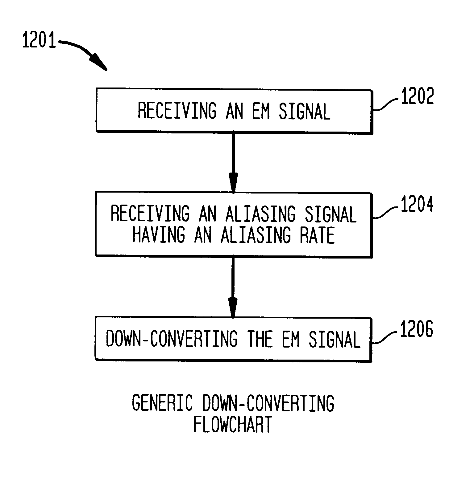
The process begins at step 4608, which includes receiving an EM signal. This is represented by the analog PM carrier signal 916.

Step 4610 includes receiving an energy transfer signal having an aliasing rate F.sub.AR. FIG. 54C illu...

first example embodiment

2.2.1 Amplitude Modulation

2.2.1.1 Operational Description

Operation of the exemplary process of the flowchart 4613 in FIG. 46C is described below for the analog AM carrier signal 516, illustrated in FIG. 5C, and for the digital AM carrier signal 616, illustrated in FIG. 6C.

2.2.1.1.1 Analog AM Carrier Signal

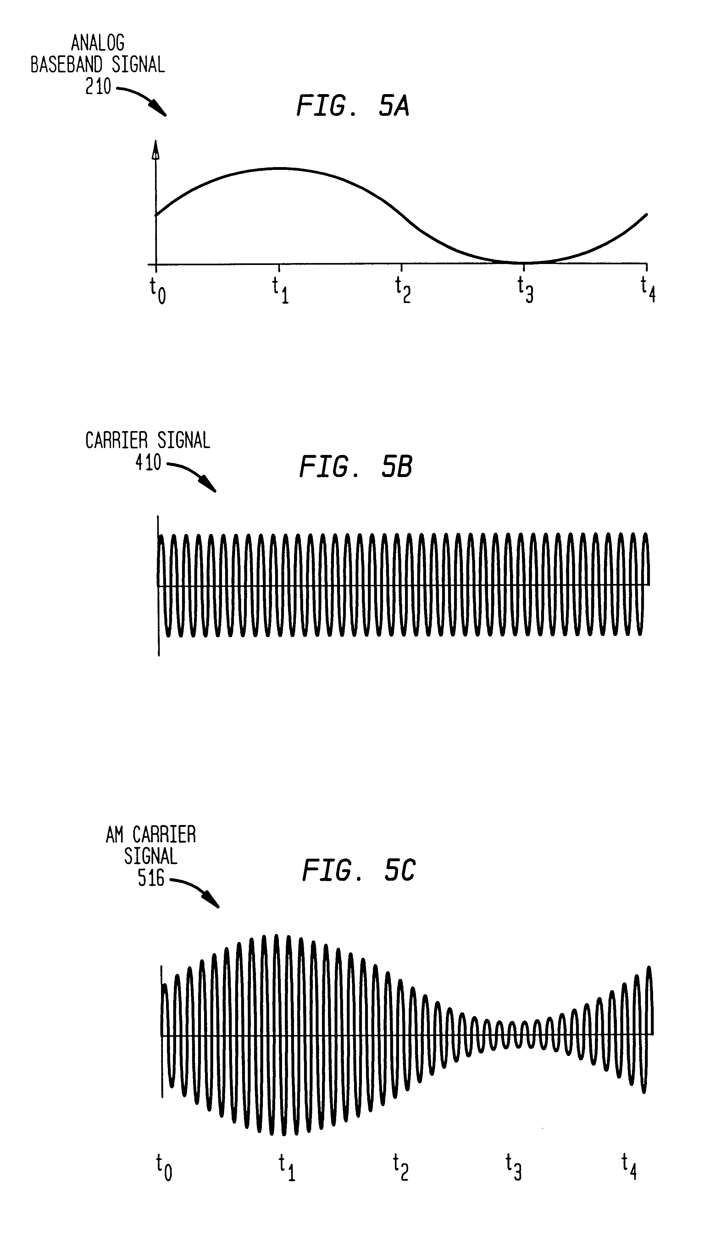
A process for directly down-converting the analog AM carrier signal 516 in FIG. 5C to a demodulated baseband signal is now described with reference to the flowchart 4613 in FIG. 46C. The analog AM carrier signal 516 is re-illustrated in 57A for convenience. For this example, the analog AM carrier signal 516 oscillates at approximately 900 MHZ. In FIG. 57B, an analog AM carrier signal portion 5704 illustrates a portion of the analog AM carrier signal 516 on an expanded time scale.

The process begins at step 4614, which includes receiving an EM signal. This is represented by the analog AM carrier signal 516.

Step 4616 includes receiving an energy transfer signal having an aliasing rat...

second example embodiment

2.2.2 Phase Modulation

2.2.2.1 Operational Description

Operation of the exemplary process of flowchart 4613 in FIG. 46C is described below for the analog PM carrier signal 916, illustrated in FIG. 9C and for the digital PM carrier signal 1016, illustrated in FIG. 10C.

2.2.2.1.1 Analog PM Carrier Signal

A process for directly down-converting the analog PM carrier signal 916 to a demodulated baseband signal is now described for the flowchart 4613 in FIG. 46C. The analog PM carrier signal 916 is re-illustrated in 59A for convenience. For this example, the analog PM carrier signal 916 oscillates at approximately 900 MHZ. In FIG. 59B, an analog PM carrier signal portion 5904 illustrates a portion of the analog PM carrier signal 916 on an expanded time scale.

The process begins at step 4614, which includes receiving an EM signal. This is represented by the analog PM carrier signal 916.

Step 4616 includes receiving an energy transfer signal having an aliasing rate F.sub.AR. In FIG. 59C, an exam...


PUM


Abstract

Methods, systems, and apparatuses for down-converting an electromagnetic (EM) signal by aliasing the EM signal are described herein. Briefly stated, such methods, systems, and apparatuses operate by receiving an EM signal and an aliasing signal having an aliasing rate. The EM signal is aliased according to the aliasing signal to down-convert the EM signal. The term aliasing, as used herein, refers to both down-converting an EM signal by under-sampling the EM signal at an aliasing rate, and down-converting an EM signal by transferring energy from the EM signal at the aliasing rate. In an embodiment, the EM signal is down-converted to an intermediate frequency (IF) signal. In another embodiment, the EM signal is down-converted to a demodulated baseband information signal. In another embodiment, the EM signal is a frequency modulated (FM) signal, which is down-converted to a non-FM signal, such as a phase modulated (PM) signal or an amplitude modulated (AM) signal.

Description

1. Field of the InventionThe present invention relates to down-conversion of electromagnetic (EM) signals. More particularly, the present invention relates to down-conversion of EM signals to intermediate frequency signals, to direct down-conversion of EM modulated carrier signals to demodulated baseband signals, and to conversion of FM signals to non-FM signals. The present invention also relates to under-sampling and to transferring energy at aliasing rates.2. Related ArtElectromagnetic (EM) information signals (baseband signals) include, but are not limited to, video baseband signals, voice baseband signals, computer baseband signals, etc. Baseband signals include analog baseband signals and digital baseband signals.It is often beneficial to propagate EM signals at higher frequencies. This is generally true regardless of whether the propagation medium is wire, optic fiber, space, air, liquid, etc. To enhance efficiency and practicality, such as improved ability to radiate and add...

Claims


Application Information

Patent Timeline
Patent Type & Authority Patents(United States)
IPC IPC(8): H03C1/62H03D7/00H04B7/12H03C1/00H04B7/02H01Q11/12H04B1/04H04B1/28
CPCH03C1/62H03D7/00H04B1/0025H04L27/12H04B7/12H04L27/00H04B1/28H04L27/14H04L27/148H04L27/156H03D7/1475H04B1/16H04L25/08H04L27/06H04L27/3881H03D7/1441H04L27/2672
Inventor SORRELLS, DAVID F.BULTMAN, MICHAEL J.COOK, ROBERT W.LOOKE, RICHARD C.MOSES, JR., CHARLEY D.
Owner PARKER VISION INC
Why Eureka
Try Eureka