Buried closure guard with electronic marker

a technology of electronic markers and closure guards, applied in the field of guards or shields, can solve the problems of inability to detect surface instruments, inconvenient installation, and inability to use reradiation,

Inactive Publication Date: 2001-08-07
MINAROVIC JOE T
View PDF9 Cites 41 Cited by
  • Summary
  • Abstract
  • Description
  • Claims
  • Application Information

AI Technical Summary

Problems solved by technology

Above-ground marking devices may be installed immediately after the conduit is buried, but they are often lost, stolen, or destroyed after a short period of use.
The primary disadvantage of (non-metallic) warning tapes is that they cannot be detected by any surface instrumentation.
Although the conduit itself may act as a conductor (i.e., when steel pipe or copper wire cabling is used), most conduits are non-conductive and therefore require a trace wire.
There are three significant disadvantages in the use of a trace wire.
Secondly, if a break occurs in the wire (due to excavation, or natural causes such as corrosion, earth movement or burrowing animals), then the wire becomes useless.
Additionally, a receiver cannot distinguish the trace wire from any other conductor in the vicinity.
While passive electronic m...

Method used


Image

  • Buried closure guard with electronic marker
  • Buried closure guard with electronic marker
  • Buried closure guard with electronic marker

Examples


Embodiment Construction

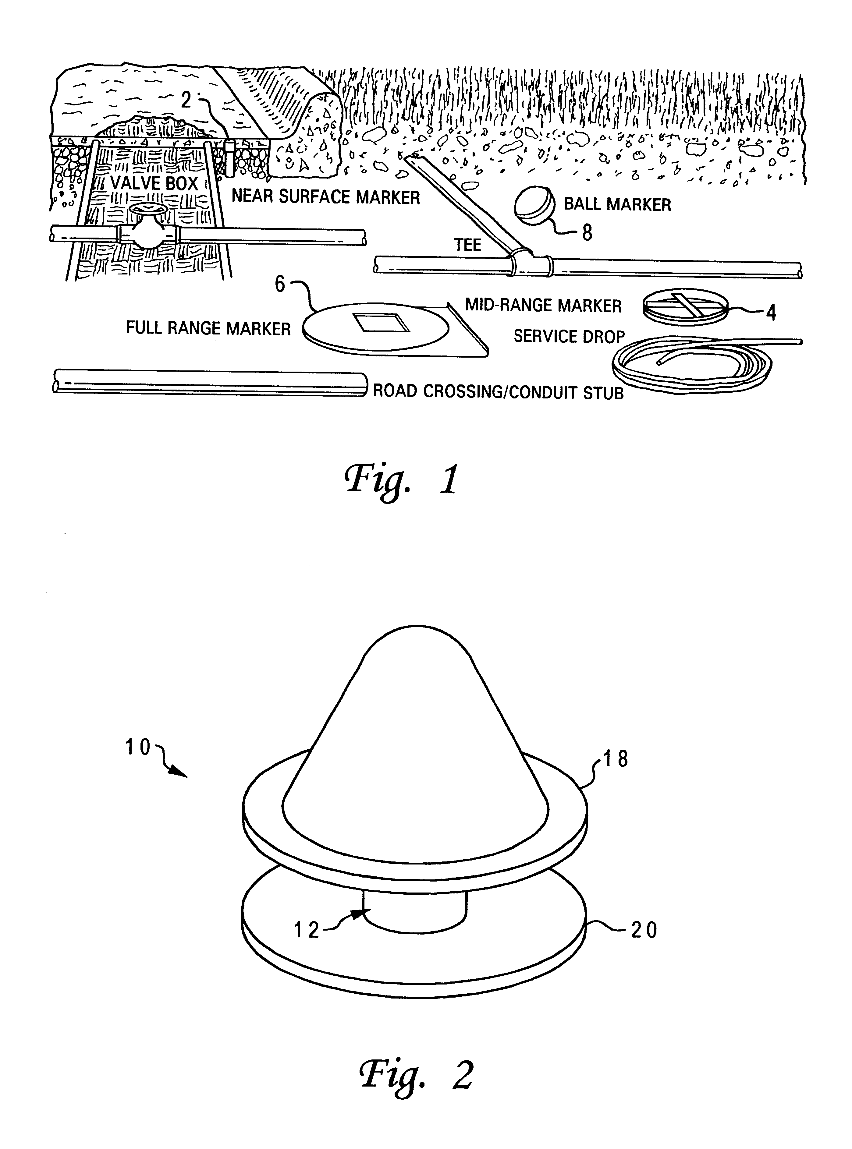
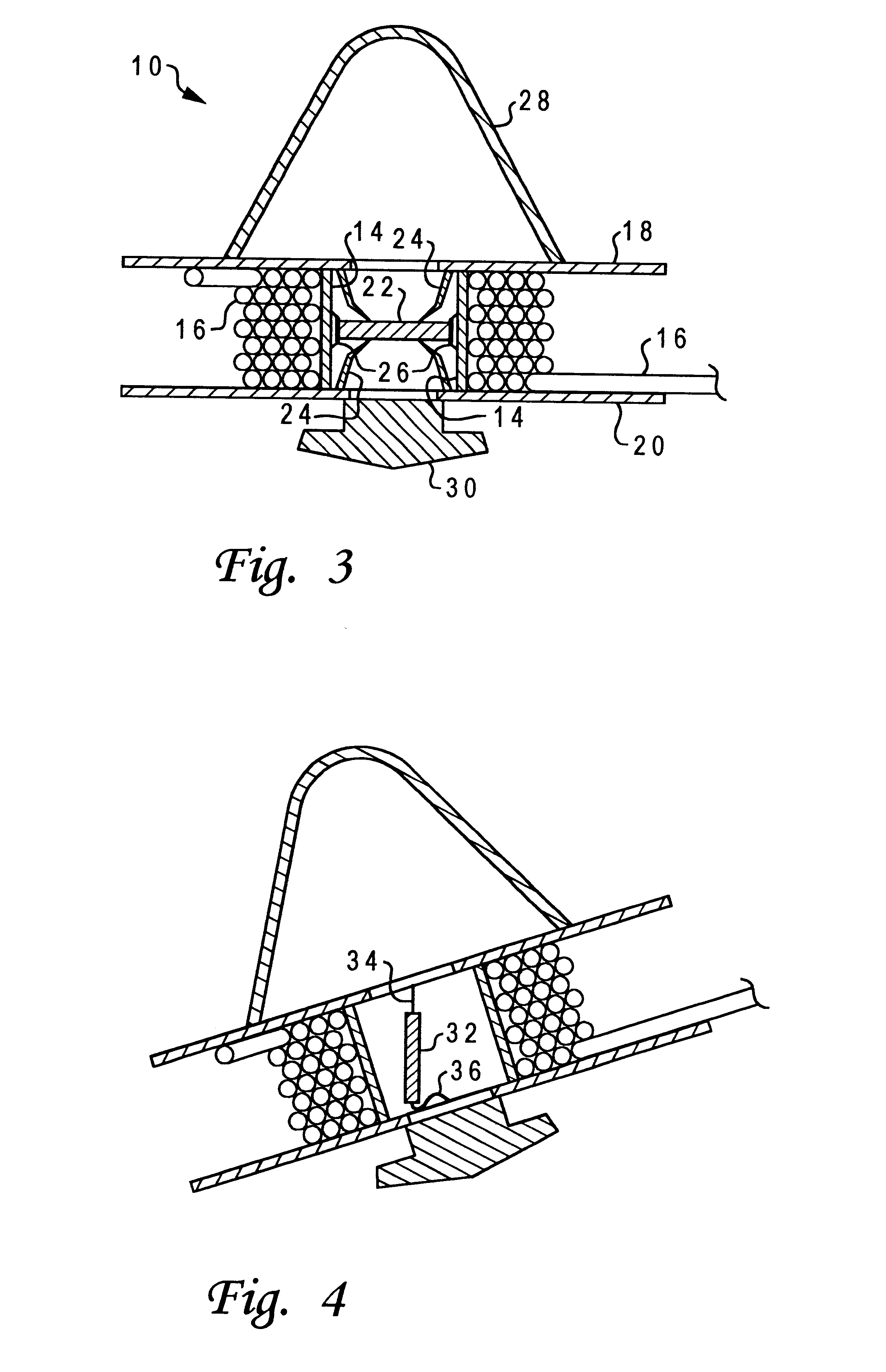
With reference now to the figures, and in particular with reference to FIGS. 2 and 3, there is depicted one embodiment of a detectable transponder reel housing 10 constructed in accordance with the present invention. Housing 10 is generally comprised of a hub or core portion 12 defining a cylindrical wall 14 about which cabling 16 may be wound, and two discs or plates 18 and 20 which confine the cabling 16 about hub 12. Plates 18 and 20, and hub 12, may be constructed of any durable material, and are preferably integrally formed using injection molding of a polymer such as polyester or high-density polyethylene, or some polymeric blend.

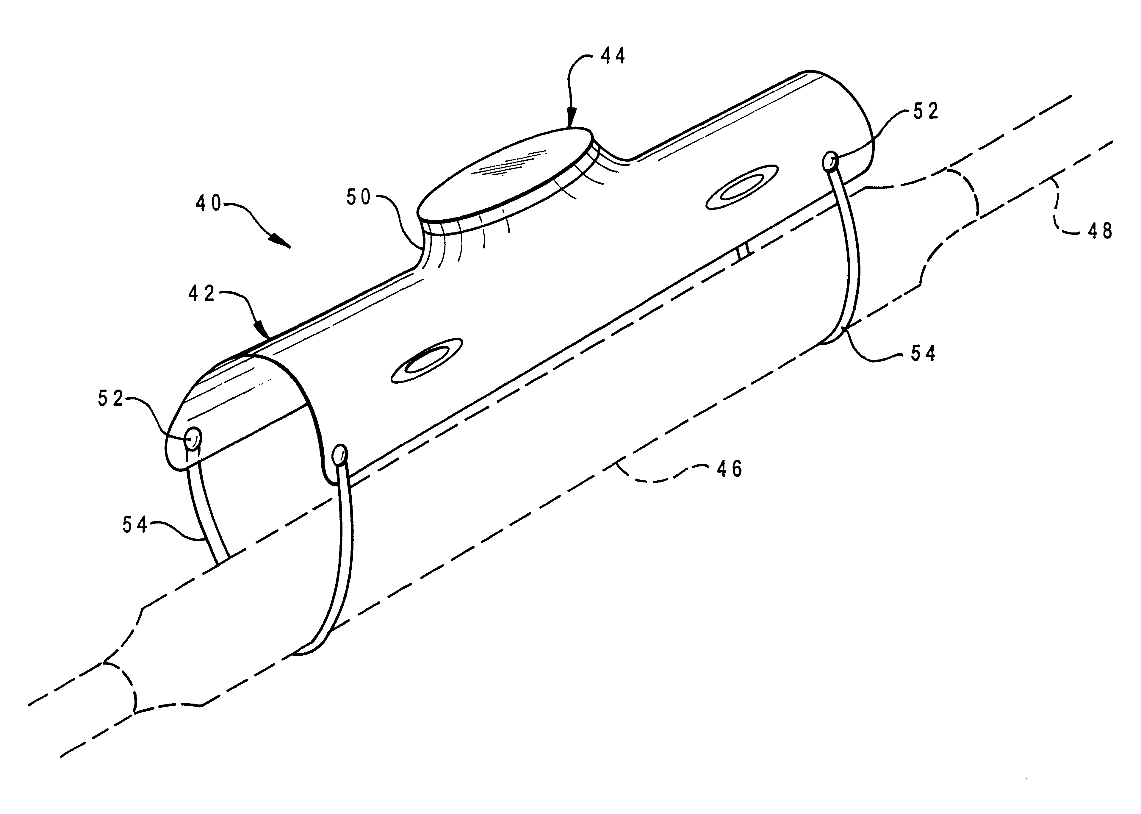
Cabling 16 constitutes a service drop which can be used to provide for timely availability of cable for power, television, or telecommunications (telephony). Utility construction crews typically bury 50 to 150 feet of cable at a property line for future service hook-up for a residence or commercial establishment, so housing 10 is adapted to retain suc...


PUM


Abstract

A device for electronically marking a buried closure has a transponder and a shield or cover affixed to the transponder in such a manner that, when attached to the buried closure, the transponder is positioned at a predetermined location and orientation with respect to the known position and orientation of the buried closure. The shield can have a raised portion housing the transponder, and is preferably elongated with an arcuate cross-section, generally larger than the buried closure.

Description

1. Field of the InventionThe present invention generally relates to devices used to electromagnetically mark and locate obscured objects, and more particularly to a guard or shield adapted to physically protect and visually mark an obscured object, such as a buried closure, which also provides a transponder or marker to enable the later location of the buried closure.2. Description of Related ArtBuried conduits are employed for supplying a wide variety of utilities, including pipelines for gas, water and sewage, and cables for telephone, optical fiber, power and television. It often becomes necessary to locate defective or damaged cables, pipes, etc., in order to repair or replace them. Conversely, it is important to know with as much accuracy as possible the approximate vicinity of such items in order to avoid disturbing them when digging or excavating for other purposes. Above-ground marking devices may be installed immediately after the conduit is buried, but they are often lost,...

Claims


Application Information

Patent Timeline
IPC IPC(8): G01V15/00F16L1/11
CPCG01V15/00F16L1/11
Inventor MINAROVIC, JOE T.
Owner MINAROVIC JOE T
Why Eureka
Try Eureka