
Illuminated article for a door having a handle

Inactive Publication Date: 2001-08-14
HOLLOWAY KATIE
View PDF10 Cites 35 Cited by
  • Summary
  • Abstract
  • Description
  • Claims
  • Application Information

AI Technical Summary

Problems solved by technology

A common problem which occurs is that an individual will wake up during the small hours of the morning and not be able to ascertain the location of the door and, more particularly, where the handle of the door is located.
Whether this be in the individual's home or if the person is traveling and in a hotel, this problem is not resolved by current devices.
The problem, generally stated, is locating the handle of a door.
This invention is expensive and cumbersome and is only applicable to certain types of doors.

Method used


Image

  • Illuminated article for a door having a handle
  • Illuminated article for a door having a handle

Examples


Embodiment Construction

The present invention will be described in conjunction with the drawings.

It will be understood, however, that the present invention will have applications in other areas of goods and that the description of the present invention with respect to the preferred embodiment is by way of example only.

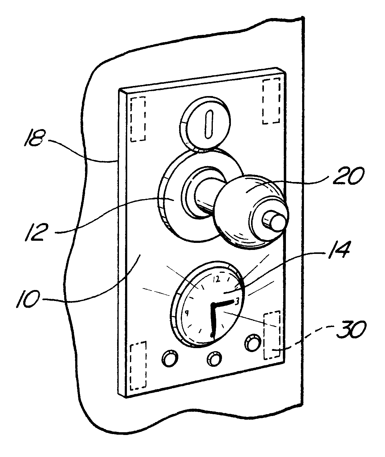
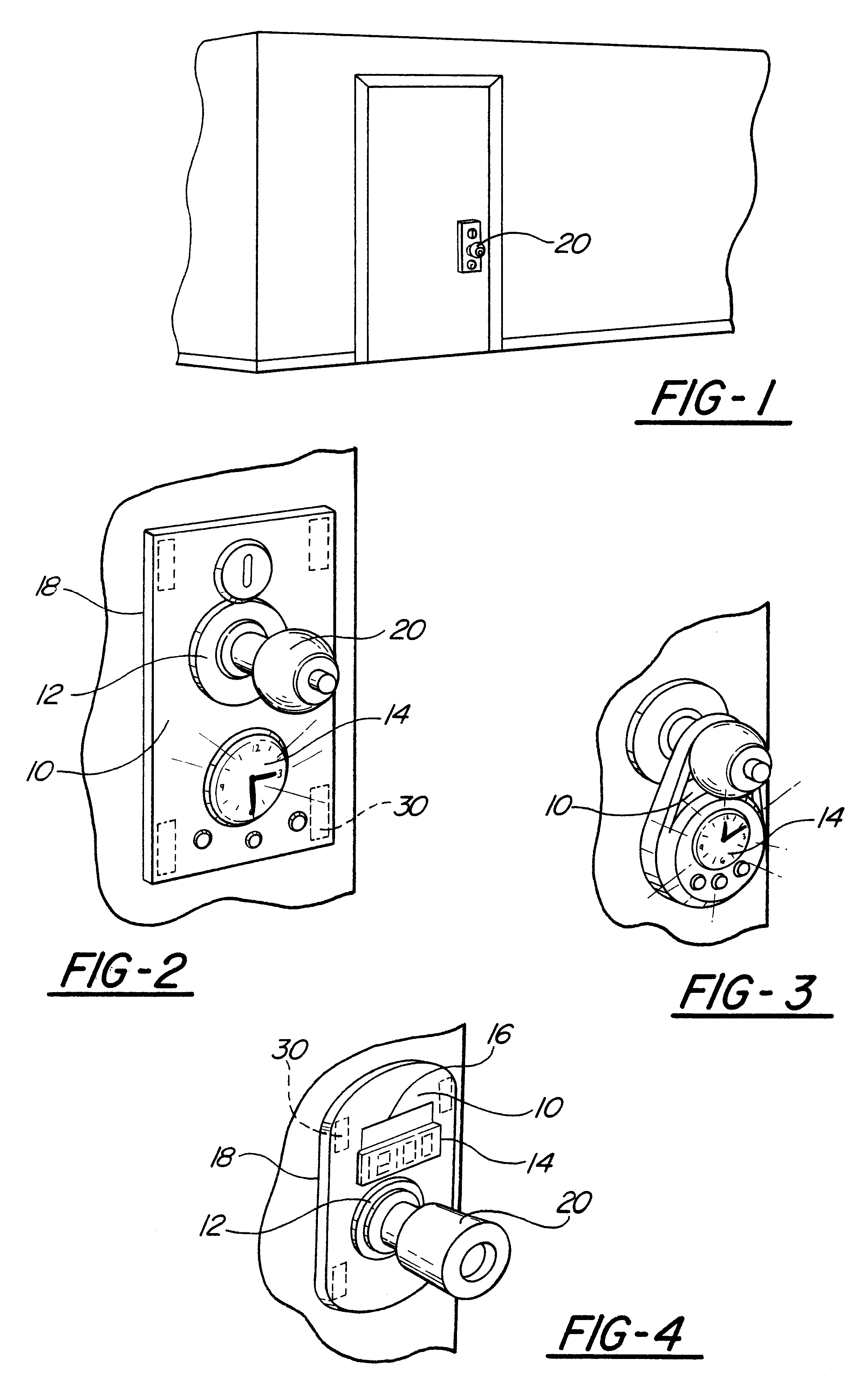
With reference now to FIGS. 1 and 2, the mounting member 10 is a rectangularly shaped piece of material (plastic, metal or other suitable material) which is sufficiently large to contain an opening 12 which is large enough to allow a door handle to be inserted through the opening. The light emitting device 14 in this embodiment consists of a timekeeping instrument which contains solar panels 16 which charge the batteries contained within the light emitting device (the timepiece). The mounting member 10 may also be constructed of a material which is translucent, thereby allowing the light emitting device 14 to be mounted either inside the mounting member 10 or on the rear face 18 of the mounti...


PUM


Abstract

An article is described for providing illumination for a door handle in reduced lighting conditions. The article includes a mounting device and a method for illuminating the door handle. The method for illuminating may comprise a timekeeping device such as a light emitting display digital clock.

Description

I. Field of the InventionThe present invention relates generally to an illuminated article for a door having a handle and, more particularly, to an article which may be mounted to a door handle and which has a means for illuminating the handle of the door.II. Description of the Prior ArtThe architectural design of buildings and residences has evolved over the centuries to incorporate the advances in the state of the art of technology. The advances have included all manners of technology from materials to electricity. The integration of the use of electricity in the design of various facilities has brought about a great number of improvements in the quality of life. One area which has not been affected is the problem of locating a door within a darkened room. Low and no light conditions have typically been accommodated by the use of night lights and lights which are timed to come on at specific times of the night. The use of a night light has typically been restricted to the placemen...

Claims


Application Information

Patent Timeline
IPC IPC(8): E05B17/10E05B17/00E05B15/02E05B15/16E05B43/00E05B47/00E05B15/00
CPCE05B17/10E05B15/02E05B15/1607E05B2047/0064E05B43/00
Inventor HOLLOWAY, KATIE
Owner HOLLOWAY KATIE
Learn More