Method and system for recovering and aligning synchronous data of multiple phase-misaligned groups of bits into a single synchronous wide bus

a synchronous bus and data recovery technology, applied in the field of data communication, can solve the problems of poor performance, phase-misalignment or skewed different groups of bits,

Active Publication Date: 2005-09-20
RIBBON COMM OPERATING CO INC
View PDF2 Cites 20 Cited by
  • Summary
  • Abstract
  • Description
  • Claims
  • Application Information

AI Technical Summary

Problems solved by technology

As a result, different groups may be phase-misaligned or skewed.
However, due to the latency mentioned above, not all eight (8) groups (32 bits) may arrive at the receiver at the same time.
Using the CLK, however, would result in poor performance.

Method used


Image

  • Method and system for recovering and aligning synchronous data of multiple phase-misaligned groups of bits into a single synchronous wide bus
  • Method and system for recovering and aligning synchronous data of multiple phase-misaligned groups of bits into a single synchronous wide bus
  • Method and system for recovering and aligning synchronous data of multiple phase-misaligned groups of bits into a single synchronous wide bus

Examples


Embodiment Construction

[0013]The present invention in the form of one or more exemplary embodiments will now be described. In an exemplary aspect, a method is disclosed for de-skewing groups of bits received at a receiver to recover the full-width bus in a common clock domain using a source-generated roll-over counter and a dual-port random access memory at the receiver.

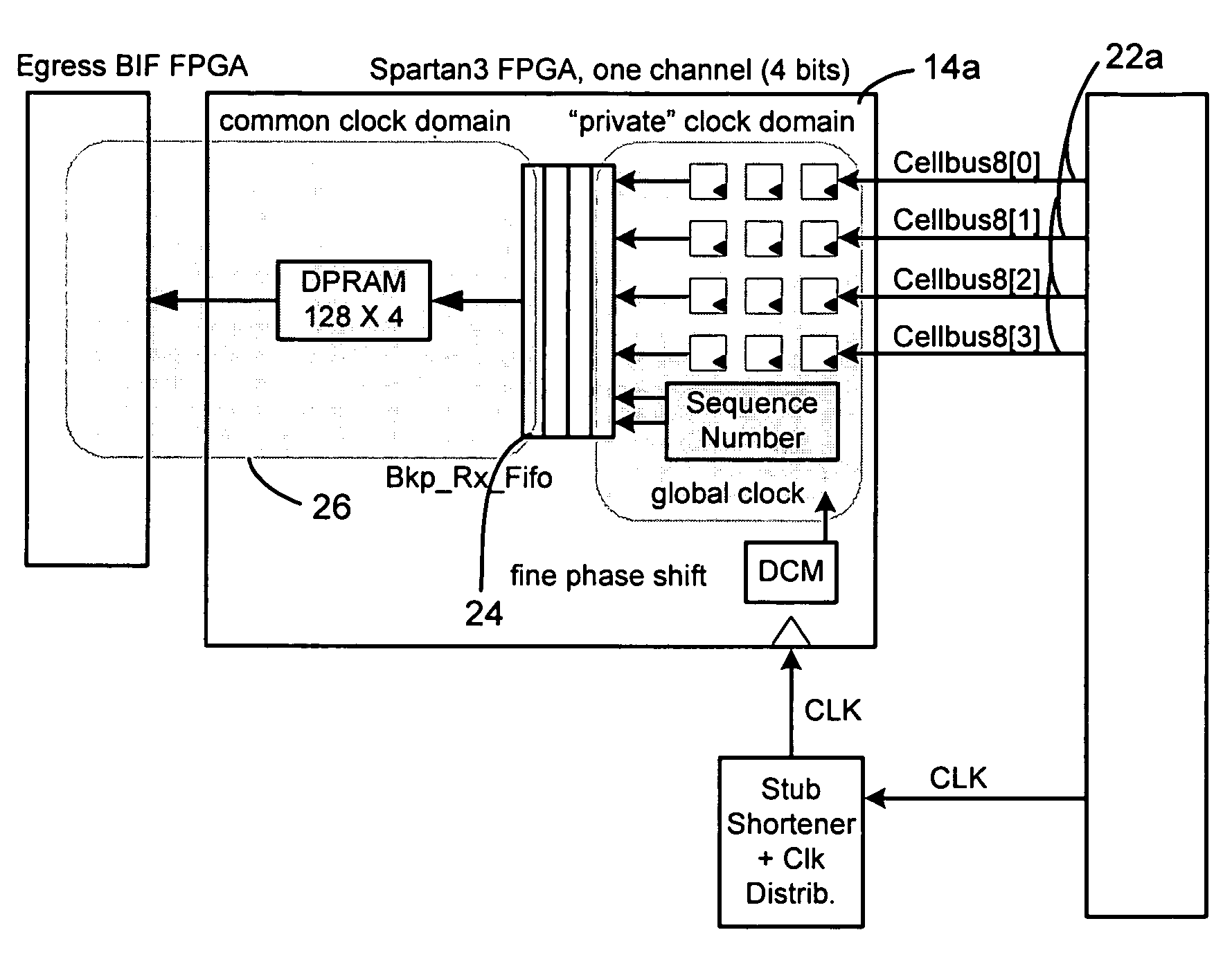
[0014]FIG. 1 is a simplified schematic block diagram illustrating an exemplary embodiment of the present invention. In this embodiment, the system 10 includes a transmitter 12, a media 28, a data recovery / alignment (“DR / A”) module 14 and a data processing block 16. The transmitter 12 can be any type of device that is capable of transmitting traffic including, for example, a signal card. The transmitter 12 transmits a number of signals over the 28 media having a number of channels to the DR / A module 14. The signals include a SOC signal 18, data groups 22a–h, and a clock (CLK) signal 20.

[0015]In this embodiment, each data group 22 is made up...


PUM


Abstract

A system for recovering and aligning synchronous data transmissions is disclosed. The system includes a transmitter configured to transmit a source clock signal and a number of data groups over a number of channels with different latencies/propagation delays. The data groups are transmitted during the same clock cycle pursuant to the source clock signal. Each data group is transmitted over a corresponding media channel. The system also includes a receiver configured to receive the source clock signal and the data groups over the corresponding channels and to re-align or recover the wide word that comes in on the channels that are skewed. The receiver further includes: for each channel, (a) a local clock configured to generate a local clock signal based on the source clock signal, the local clock signal being phase-shifted from the source clock signal by a predetermined amount of phase shift, (b) a logic device configured to clock in the data group received over the channel using the local clock signal, (c) a sequence number generator configured to generate a sequence number associated with the data group, (d) a FIFO configured to store and output the clocked-in data group and the associated sequence number, (e) a memory device configured to store the clocked-in data group from the FIFO using the associated sequence number as a memory address, the memory device further configured to output a predetermined portion of its contents after a predetermined capacity threshold is reached. The transmitter is further configured to transmit a start-of-cell signal to the receiver. The sequence number generators are synchronized upon receiving an alignment cell, which is identified by a start-of-cell signal having a specific value for a predetermined cycle period. In one implementation, the receiver is implemented using a number of field programmable gate arrays and the local clocks are implemented using digital clock managers associated with the field programmable gate arrays.

Description

BACKGROUND OF THE INVENTION[0001]The present invention generally relates to data communications and, more specifically, to a method and system for recovering and aligning data transmissions over a synchronous bus.[0002]In electronic equipment, various internal components communicate and exchange information and data with each other. Such communications are usually conducted over a media, such as a backplane, traces, wires or cables. A transmitter or source of traffic, for example, a card transmitting data on a 32-bit wide synchronous bus and a SOC (start-of-cell) signal onto a media, transmits data toward a receiver which is located at the other end of the media. The electrical signals going across the media are generally routed in groups, where each group of signals / bits is length-matched. This means that the propagation latency of traversing the media is the same for all signals / bits within the same group; however, different groups may have different latencies even though the diff...

Claims


Application Information

Patent Timeline
Patent Type & Authority Patents(United States)
IPC IPC(8): H03K19/177G06F1/10
CPCG06F1/10
Inventor SENDROVITZ, RAN
Owner RIBBON COMM OPERATING CO INC
Why Eureka
Try Eureka