Spread spectrum clock generator

a clock generator and spectrum spectrum technology, applied in the field of synchronous digital circuitry, can solve the problems of increasing the incidence of electromagnetic interference, data errors in associated data processing devices, and difficult and expensive to achieve sscg circuitry

Inactive Publication Date: 2005-03-31
TOSHIBA AMERICA ELECTRONICS COMPONENTS
View PDF13 Cites 19 Cited by
  • Summary
  • Abstract
  • Description
  • Claims
  • Application Information

AI Technical Summary

Problems solved by technology

As clock frequencies continue to rise, an increased incidence of electromagnetic interference exists.
EMI can cause data errors in associated data processing devices, as well as provide for radio frequency (“RF”) interference for analog devices such as radios and televisions.
While effective, such analog-based implementations render it difficult and expensive to accomplish an SSCG circuitry, particularly in applications when a system is desired to coexist on other standard digital circuitry and in conjunction with a single substrate.

Method used


Image

  • Spread spectrum clock generator
  • Spread spectrum clock generator
  • Spread spectrum clock generator

Examples


Embodiment Construction

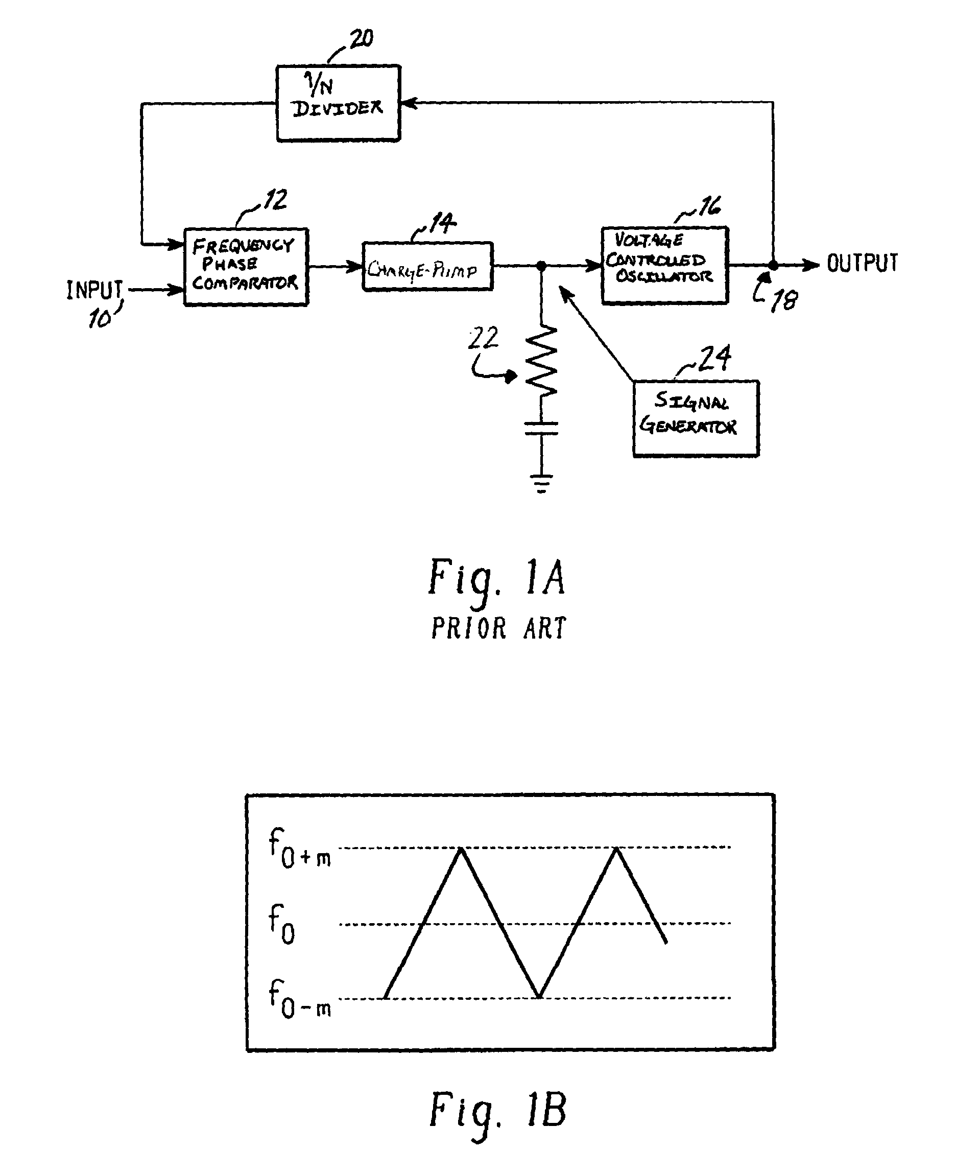
[0017] Turning now to the drawings wherein the illustrations are for the purpose of illustrating the preferred embodiment only, and not for the purpose of delivering the same, FIG. 1A shows a block diagram of a conventional spread spectrum clock generator. In a conventional system, a clock input 10 was provided as one input to a frequency phase comparator 12. An output of the comparator 12 was provided to a charge pump 14, the output of which is provided to a voltage controlled oscillator (“VCO 16”). Output 18 of the VCO 16 forms a system clock output, as well as a feedback loop into frequency comparator 12 via a 1 / N divider 20.

[0018] A conventional spread spectrum clock generator employed an RC circuit 22 as a filter to ground. A signal generator 24 served to generate a waveform (such as that evidenced in FIG. 1B) into the input of the VCO 16. By injecting this signal into the VCO input, an output frequency at output 18 was modulated in conjunction with the waveform of FIG. 1B.

[0...


PUM


Abstract

A clock signal generator varies a frequency of a digital clock over a selected range of frequencies. The generator employs a divider for lowering a frequency of a clock signal. A counter increments synchronously with the signal, and causes a selected sequence of outputs to be generated by a pattern generator. The pattern generator output forms an input to a digitally controllable delay line which receives the lower frequency clock signal. The pattern generator causes the digital delay line to vary a frequency of the lowered frequency clock signal between selected boundaries. The varying frequency clock signal is then raised up again such that a final clock has a varying frequency, and will exhibit less EMI spiking during switching of an associated, synchronous digital data device. The solid state nature of the generator allows for simple fabrication, inexpensive manufacture and ready integration into digital circuitry, such as multifunction integrated circuits.

Description

BACKGROUND OF THE INVENTION [0001] The subject application is directed generally to the art of synchronous digital circuitry, and more particularly to synchronous digital circuitry in which a lessened effect of electromagnetic interference (“EMI”) is desirable. [0002] Most digital devices today operate synchronously. That is, data processing operations occur under a timing dictated by a digital clock signal. Such digital clock signals are typically square waves that oscillate at a selected frequency. As improvements are made to digital processing devices, clock frequencies may be increased. Faster clock frequencies allow for improved data processing throughput. Current digital clock frequencies are already in the multi-gigahertz range. As clock frequencies continue to rise, an increased incidence of electromagnetic interference exists. Such EMI requires that special shielding or casing be developed to dampen such interference. EMI can cause data errors in associated data processing ...

Claims


Application Information

Patent Timeline
Patent Type & Authority Applications(United States)
IPC IPC(8): H04B1/707
CPCH04B2001/70706H04B1/707
Inventor KAIZUKA, MASAO
Owner TOSHIBA AMERICA ELECTRONICS COMPONENTS
Why Eureka
Try Eureka