Coin handling mechanism

a technology which is applied in the direction of coin inlet, coin-freezing or similar apparatus, instruments, etc., can solve the problems of coin counting and credit mechanism short circuit, malfunction, and no adjustment mechanism,

Inactive Publication Date: 2001-08-28
ANTARES APPLIED RES
View PDF20 Cites 6 Cited by
  • Summary
  • Abstract
  • Description
  • Claims
  • Application Information

AI Technical Summary

Benefits of technology

Applicants' invention solves both the problem of providing a liquid diverting coin handling mechanism and also provides for adjustable means at the coin discharge end of the coin chute, so that coins will be directed accurately into the coin receptor. The invention comprises a housing having front, back and side walls with a coin receiving slot at the top of the housing. The housing is mounted to the door of a vending machine. There are a series of vertically disposed ribs at the bac

Problems solved by technology

In the past, there has not been any adjustment mechanism to adjust the discharge end of the coin chute to allow for any adjustment and direction of the coin as it is discharged from the coin chute.
Another problem has developed with respect to vandals pouring or injecting a liquid, commonly salt water, into the coin chute.
The salt water causes the coin counting and credit mechanisms to short circuit and malfunction.
Often, this results in the vending machine discharging the improper amount or all of the merchandise.
Furthermore, the salt water can cause the receptor to be destroyed resulting in expensive repairs to the vending machine.
In the past, no coin chute has ever been devised which provides adjustability of the coin discharge portion of the coin chute.
However, this was not a satisfactory solution to the problem as the coin discharge chute did not al

Method used


Image

  • Coin handling mechanism
  • Coin handling mechanism
  • Coin handling mechanism

Examples


Embodiment Construction

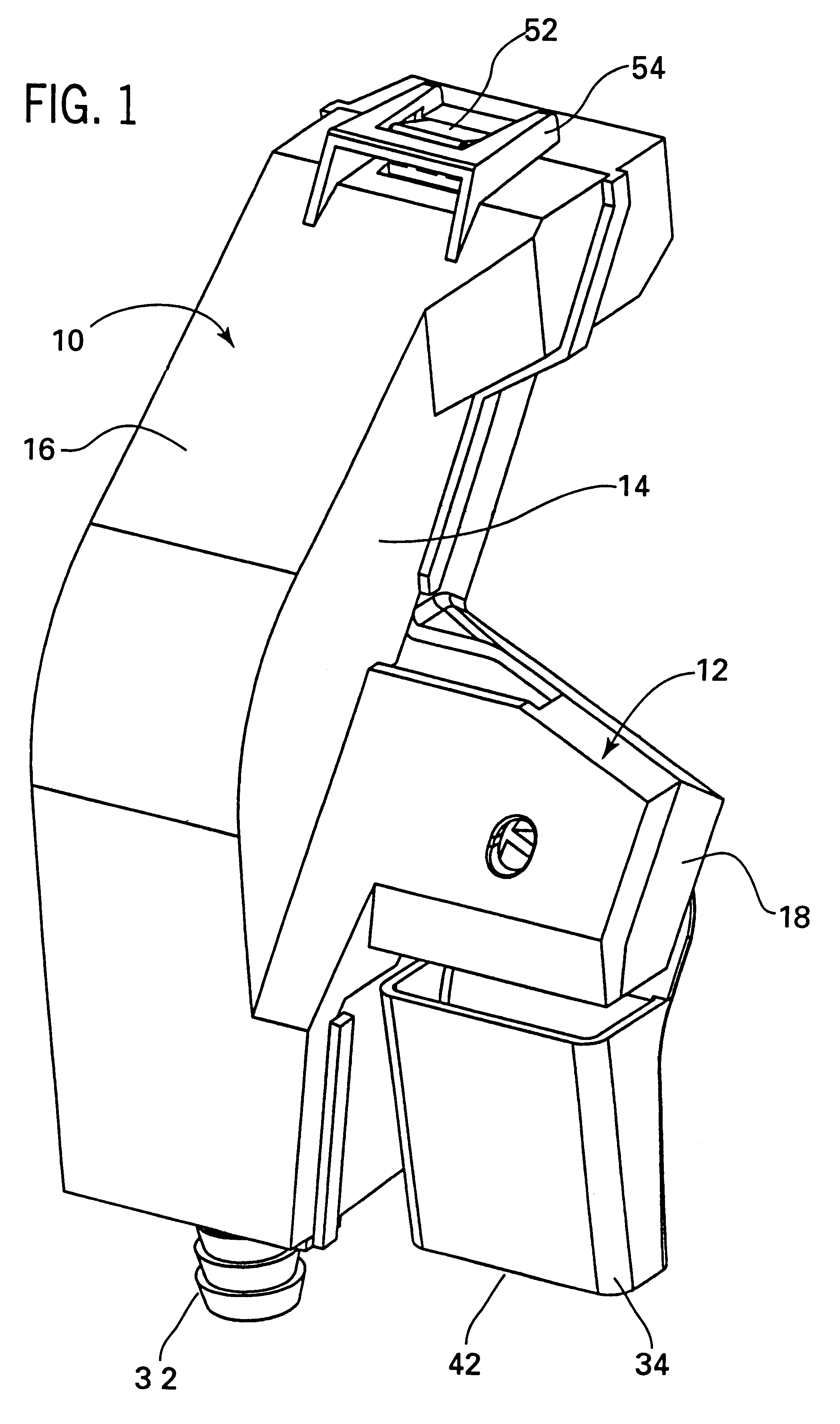
Turning first to FIG. 1 there is illustrated an inventive coin handling mechanism 10 embodying our unique design. It is comprised of a cover 12 having side walls 14 and 15, and a front wall 16.

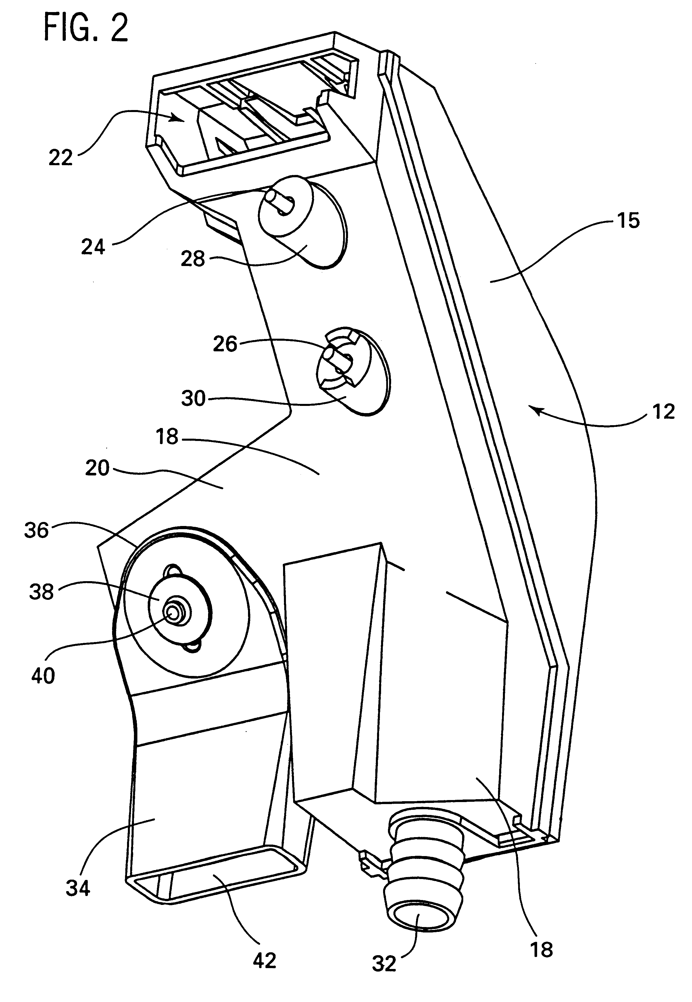
FIG. 2 illustrates the opposite side of the mechanism 10. There is a base 18 having a front wall 20. At the top of the base 18 is a coin receiving slot 22 at a top portion 23 of the base 18 through which the user of the vending machine deposits their coins generally with the coins in a horizontal plane. There are a pair of mounting screws 24, 26 which extend through the base 18 and into the rear of the front door of the vending machine (not illustrated). A pair of supports 28, 30 extend out from the base 18 in order to give structural support and stability to the base 18 when mounted against the vending machine door. At the bottom of the base 18 is a drain 32 which generally connects to a drain pipe or tube to dispel fluid collected within the coin handling mechanism 10.

There is also illustrat...


PUM


Abstract

A coin handling mechanism for conveying coins to a remotely positioned coin receptor which accumulates the deposited coins. There is a water trap positioned along a back wall of the housing for diverting the flow of liquid injected through the coin entrance slot downwardly along the back of the housing to a fluid collecting chamber. The water trap comprises intersecting vertical support members and horizontal cross bars. There is also provided a coin discharge chute having an adjustment mechanism to adjust the point of discharge of the coins.

Description

II. FIELD OF THE INVENTIONThis invention relates to coin receiving devices for use on vending machines, and more particularly, to a coin handling mechanism which diverts liquid from the coin entrance slot and keeps the liquid from entering the coin receptor. Furthermore, the mechanism includes provisions for providing an adjustable diverter mechanism at the output of the coin handling mechanism such that the coins can be accurately deposited into the coin receptor.III. BACKGROUND OF THE INVENTIONThere has existed a need for a reliable method for conveying coins from an entry point or slot on the front of a vending machine to a coin counting and validation mechanism located within the machine. This is normally accomplished with a device such as a coin chute, which usually consist of two or more plastic parts, bolted inside the vending machine door. Coin chutes used for this specific purpose have two openings. The first is located next to the entry slot on the vending machine to recei...

Claims


Application Information

Patent Timeline
IPC IPC(8): G07F1/00G07F1/04
CPCG07F1/045
Inventor DELMENICO, PETERGEORGE, WILLIAM R.
Owner ANTARES APPLIED RES
Why Eureka
Try Eureka