Object recognition apparatus and method

a recognition apparatus and object technology, applied in the field of object recognition apparatus and, can solve the problems of reducing reliability, insufficient accuracy and efficiency of obtaining camera attitude parameters, and inhibiting the generation of camera attitude parameters

Inactive Publication Date: 2001-09-04
TOYOTA JIDOSHA KK
View PDF12 Cites 547 Cited by
  • Summary
  • Abstract
  • Description
  • Claims
  • Application Information

AI Technical Summary

Problems solved by technology

In a conventional system, however, these data handled by the position detection processing unit or the anti-lock brake unit are not utilized to obtain the camera attitude parameters, and hence, the accuracy and efficiency of obtaining the camera attitude parameters are insufficient.
The parameter generating means may obtain the bearing of the vehicle from the position detection device, and may inhibit the generation of the camera attitude parameters if the change in the bearing of the vehicle is greater than a predetermined value.
The brake control device may have information associated with the acceleration of the vehicle, and the reliability obtaining means may reduce the reliability when the acceleration of the vehicle is greater than a predetermined value.
The brake control device may have information associated with the operation of the brake of the vehicle, and the reliability obtaining means may reduce the reliability when the brake of the vehicle is operated.
An optimum error range can be set by reducing the reliability of the camera attitude parameters when the acceleration of the vehicle is large or the brake is operated, because the pitch angle of the vehicle will increase to an abnormal level in these cases, and hence, the calculation accuracy of the camera attitude parameters will be degraded.

Method used


Image

  • Object recognition apparatus and method
  • Object recognition apparatus and method
  • Object recognition apparatus and method

Examples


first embodiment

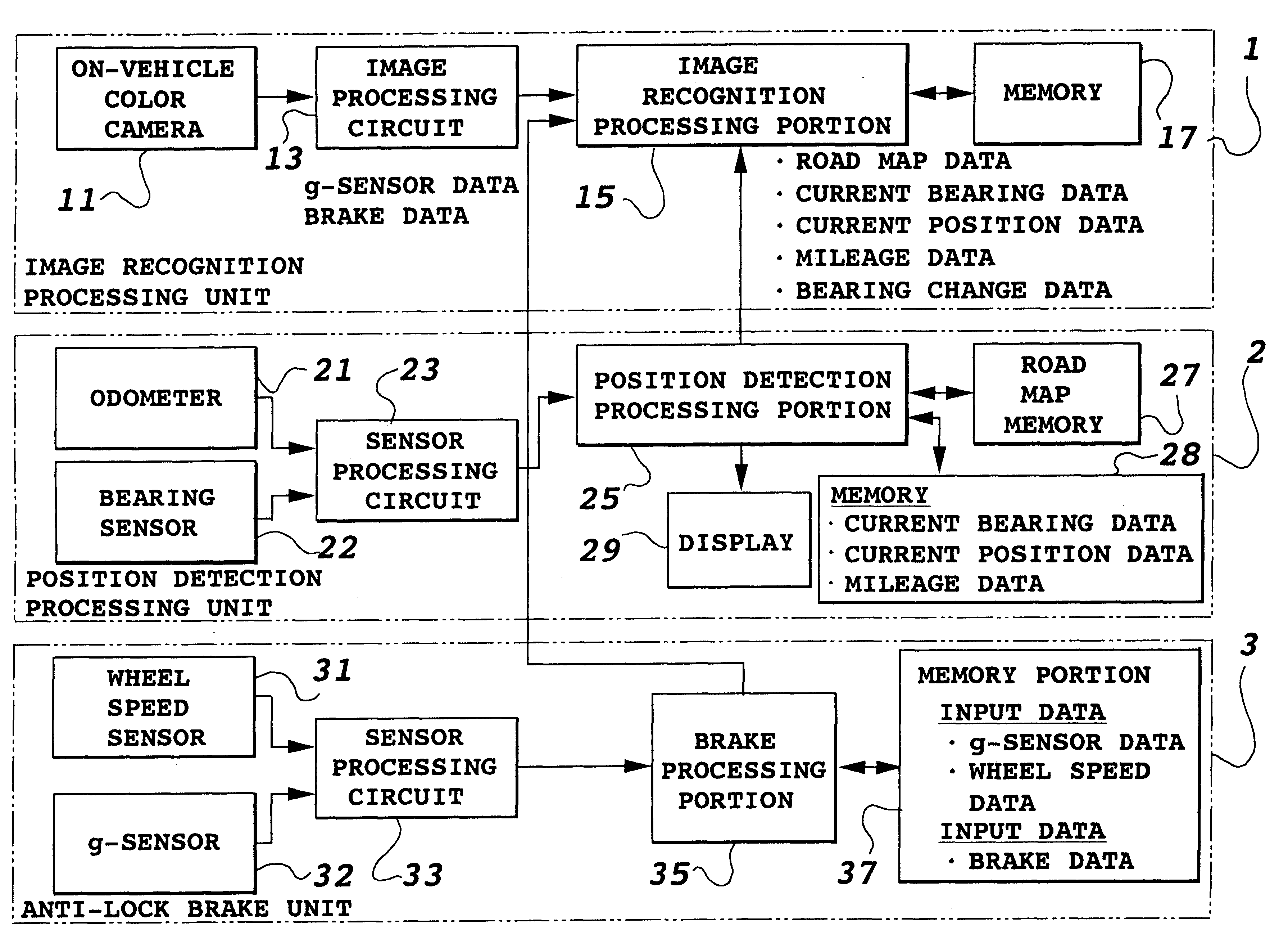
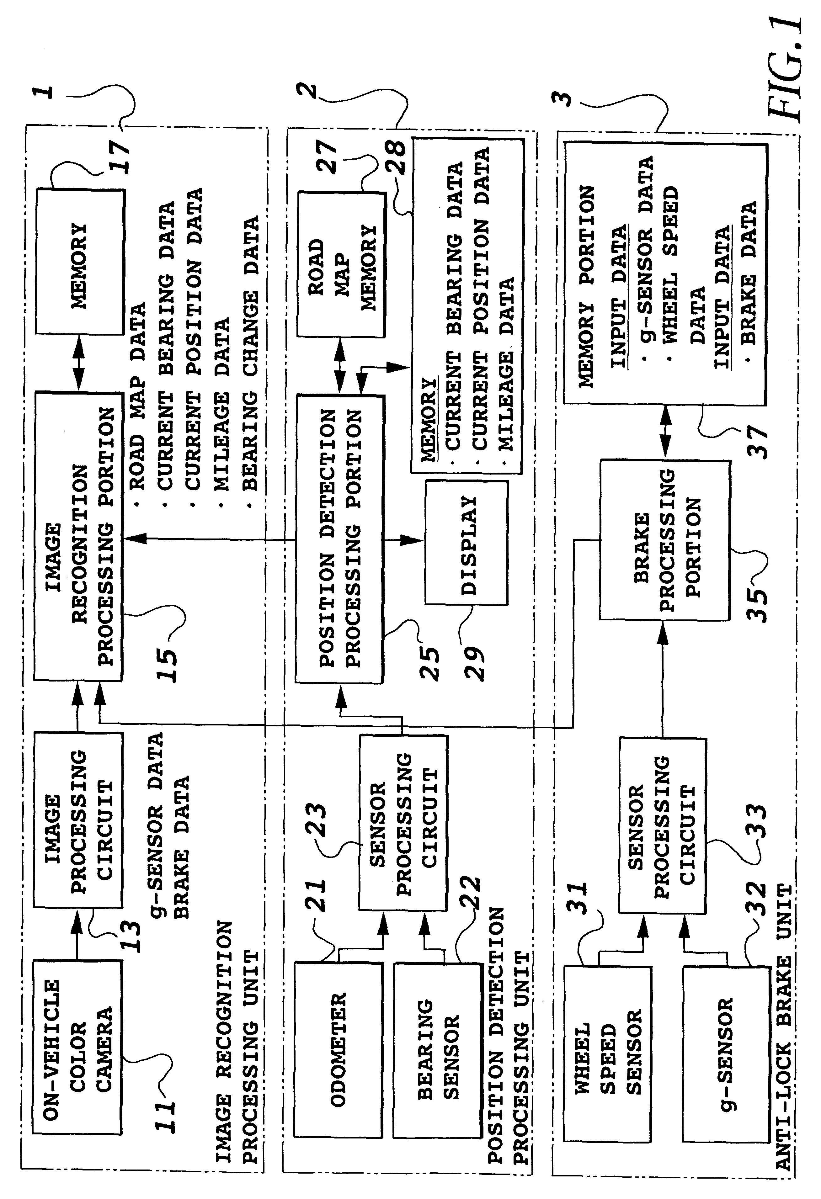
According to the on-vehicle image recognition processing system, since road parallel lines other than a white line can be recognized in the line detection processing, the calculation of a road vanishing point can be positively achieved based on those road parallel lines. Furthermore, the camera attitude parameters can be obtained from the calculated road vanishing point. This makes it possible to correctly recognizing objects successively moving in the image plane. In these processings, the support information from the position detection processing unit 2 and / or the anti-lock brake unit 3 are used as needed.

With the arrangement of the first embodiment, since objects ahead of the vehicle can be recognized correctly, it becomes possible to carry out automatic drive of a vehicle by using the recognition results, and to prepare support information for directing a course by the position detection processing unit 2.

Although the recognition of objects ahead of the vehicle is chiefly descri...

embodiment 2

In the first embodiment, the road vanishing point and road parallel lines are obtained by repeating the Hough transform twice. The Hough transform, however, takes a long processing time, and hence, it is unpractical to carry out the Hough transform at each processing period during traveling. Accordingly, in the second embodiment, a method for obtaining the road vanishing point and road parallel lines simply and rapidly at the cost of accuracy to some extent is used after the second time.

second embodiment

The second embodiment employs an image recognition processing system as shown in FIG. 17, which corresponds to the system of FIG. 1 without the anti-lock brake unit 3.

FIGS. 18A and 18B are diagrams for explaining the principle of the simplified road vanishing point calculation method. The method extracts line candidate points from an image acquired by the on-vehicle color camera 11, imaginarily assigns road parallel lines obtained at the preceding period as shown in FIG. 18A, and specifies several line candidate points near the road parallel lines. New road parallel lines L.sub.1 and L.sub.2 passing close to the specified points a.sub.1, b.sub.1, c.sub.1, a.sub.2, b.sub.2, and c.sub.2 are calculated as shown in FIG. 18B. The two lines L.sub.1 and L.sub.2 are adopted as the road parallel lines of the present period, and their intersection is obtained as the road vanishing point.

FIGS. 19-22 are a flowchart explaining the simplified road vanishing point calculation method executed by t...


PUM


Abstract

An object recognition apparatus that can recognize an object in an image acquired by an on-vehicle camera mounted on a vehicle with high efficiency and accuracy. A recognition processing is carried out in a cut off range, which is cut off from the image, and in which an object to be recognized is supposed to be present. The cut off range is obtained using support information supplied from a position detection device and/or an anti-lock brake device of the vehicle. Since the object in the image changes its position as the vehicle moves, the displacement must be estimated during the object recognition. The estimation requires camera attitude parameters of the on-vehicle camera with respect to the road, and the estimation is performed using support information supplied from the position detection device and/of the anti-lock brake device. This will improve the efficiency and accuracy of obtaining the camera attitude parameters.

Description

1. Field of the InventionThe present invention relates to an object recognition apparatus and method performing recognition of objects on and around a road, on which a vehicle is traveling, on the basis of images picked up by an on-vehicle camera, and to a camera attitude parameter generating apparatus and method producing camera attitude parameters which represent the attitude of the on-vehicle camera with respect to the road, and are used for the recognition of objects.2. Description of Related ArtVarious techniques have been proposed to pick up images ahead of or behind a vehicle by an on-vehicle camera, and to recognize objects in the images. For example, if the foregoing vehicles are recognized by processing the foregoing images of the vehicle, which are acquired by the on-vehicle camera, the results can be used in an automatic operation of the vehicle, thereby preventing an accident. Specifically, if other vehicles abnormally approach the vehicle, an accident can be prevented ...

Claims


Application Information

Patent Timeline
Patent Type & Authority Patents(United States)
IPC IPC(8): G05D1/02G06T7/00H04N7/18G06V10/48
CPCG05D1/0246G05D1/0272G05D1/0274G06K9/00798G06T7/004H04N7/183G05D2201/0213G06T7/70G06V20/588G06V10/48
Inventor SHIMOURA, HIROSHITENMOKU, KENJI
Owner TOYOTA JIDOSHA KK
Why Eureka
Try Eureka