Ventilated plastic bag

a technology of ventilated plastic bags and bags, which is applied in the direction of domestic cooling devices, transportation and packaging, lighting and heating devices, etc., can solve the problems of greater tear propagation and provide problems in the use of bags, and achieve the effect of strengthening corona and pressure bonding

Inactive Publication Date: 2001-09-11
HILEX POLY
View PDF49 Cites 89 Cited by
  • Summary
  • Abstract
  • Description
  • Claims
  • Application Information

AI Technical Summary

Benefits of technology

By overcoming ventilation and strength problems in plastic bags proposed by use in the fast food industry, it has also been found by this invention that other preferred features of plastic bags heretofore utilized in other contexts can also be utilized with the ventilated plastic bag of this invention. These improvements include the use of non-residue central mounting tab portions on the bags for adapting the bags for mounting on a suitable dispenser rack for removal by a user without leaving residue on the rack, self-opening features which allow the bags to be serially opened one at a time by the user when removing the bags from a rack, angle seals at the bottom corners of the bag to produce a flat bag when the bag is in an open position for loading by a user, etc. It has also been found desirable to utilize either clear film to enable identification of articles placed inside the bag for a more accurate order filling in the fast food restaurant or co-extruded film in which an inside layer of film is of a stiffer material to provide shape to the bag and an outside layer is of a softer film material to enhance corona and pressure bonding between outside layers for self-opening of the bags when serially removed one at a time from a bag pack mounted on a dispensing rack.

Problems solved by technology

However, it has been determined by this invention that these closely spaced micro-perforations tend to weaken the resistance to tear in the bag and if placed along substantially the entire surface area (as had been done in prior micro-perforated plastic bread and vegetable bags) and in the reduced strength regions created by the cut out utilized to form the handle means in the bag, and create greater tear propagation providing problems in use of the bags.

Method used


Image

  • Ventilated plastic bag
  • Ventilated plastic bag
  • Ventilated plastic bag

Examples


first embodiment

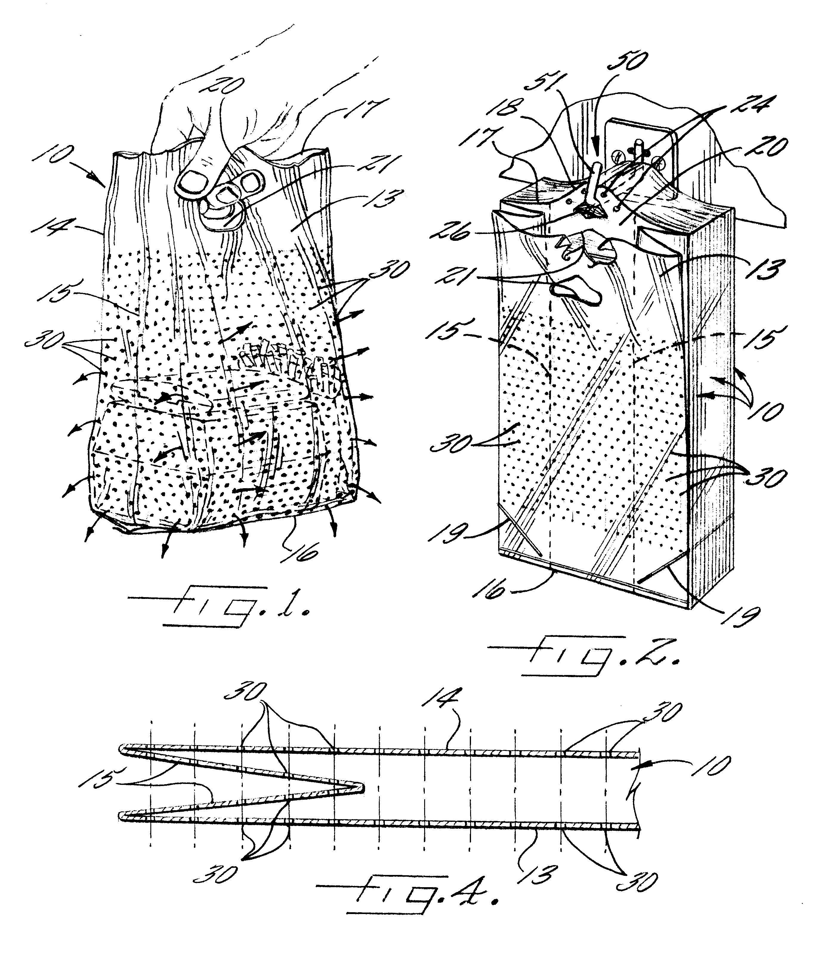
FIG. 1 is a perspective view of a ventilated plastic bag constructed in accordance with this invention, loaded with hot food from a fast food restaurant and being carried at a handle section by a user;

FIG. 2 is a perspective view of a pack of the plastic bags of the first embodiment of FIG. 1 and having a first pattern of closely spaced micro-perforations and being mounted on a rack for removal by a user and filling with hot food from a fast food restaurant;

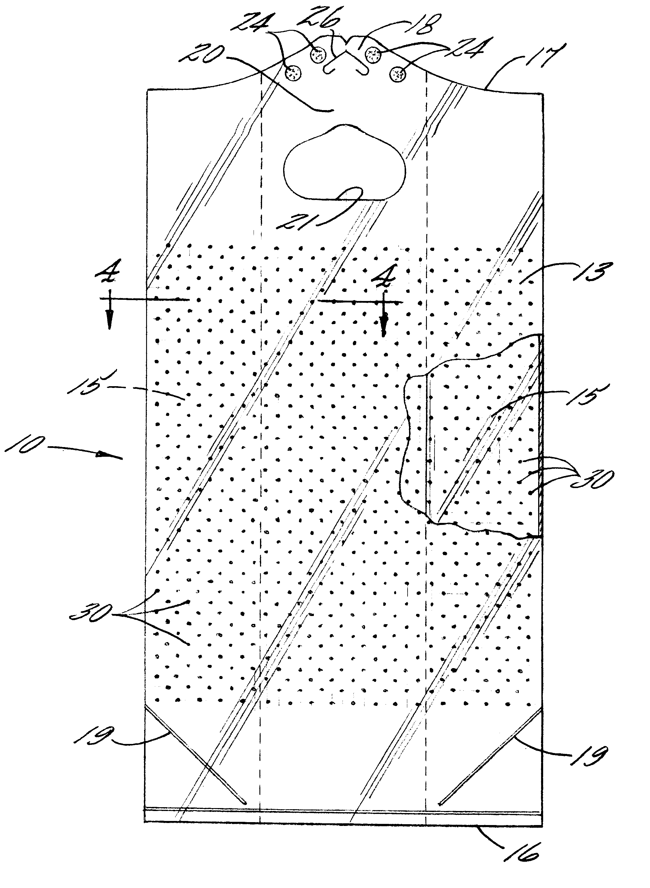
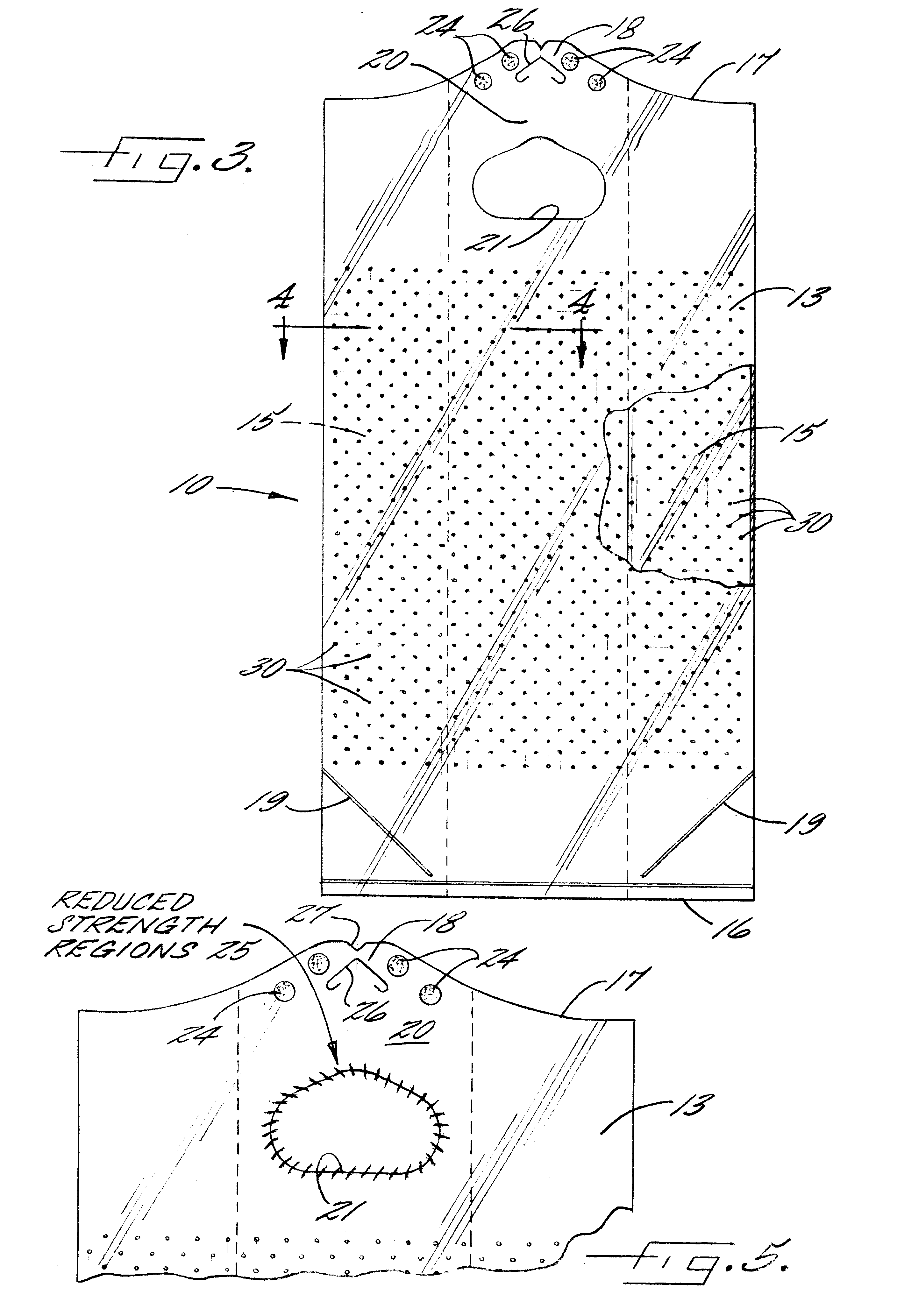
FIG. 3 is an enlarged front elevational view, partially broken away, of one of the plastic bags of the first embodiment illustrated in FIG. 2;

FIG. 4 is a sectional view through the plastic bag of the first embodiment of FIG. 3 and taken generally along the line 4--4 of FIG. 3;

FIG. 5 is an enlarged front elevational view of the top area of the first embodiment of ventilated plastic bag of FIG. 3 and schematically illustrating reduced strength regions created by the cut out of the front and rear wall sections to create a handle mea...

second embodiment

FIG. 9 is a front elevational view of a ventilated plastic bag of the T-shirt type construction and having the first pattern of closely spaced micro-perforations;

FIG. 10 is a perspective view of a pack of the bags of FIG. 9 mounted on a dispensing rack; and

FIG. 11 is a view like FIG. 10 illustrating a first bag being opened on said rack for filling by a user and subsequent removal for serially opening the next bags in the pack on the rack.


PUM


Abstract

A ventilated plastic bag particularly adapted for carrying hot food from fast food restaurants includes the following components. Front and rear wall sections are connected together to define a closed bottom area and an open top area. A handle or handles are provided in the top area and include a cut out of the front and rear wall sections creating reduced strength regions with resulting high potential for carrying around at least part of the cut out. Closely spaced micro-perforations extend through the wall sections in at least a major portion of the plastic bag other than the reduced strength regions to provide ventilation to an interior food carrying area of the plastic bag while not further weakening the reduced strength regions and increasing the potential for tearing of the bag.

Description

This invention relates to a ventilated plastic bag particularly adapted for carrying hot food from fast food restaurants, a pack of such bags, and a dispensing system utilizing such bags.BACKGROUNG OF THE INVENTIONSince the 1970's, plastic bags have been replacing paper bags in the United States for the grocery and retail products industries because of the superior strength and inherent moisture resistant properties and strength of plastic, among other things.These plastic bags have taken various shapes and forms including T-shirt type plastic bags which include front and rear wall sections integrally connected together by gussetted side walls and connected at the bottom to define a closed bottom on the bag. At least a part of the top of the front and rear wall sections are open at the tops to define an open mouth and laterally spaced handles which are integral with the wall sections extend upwardly from opposed sides of the mouth portions for carrying of the bags. This type of plas...

Claims


Application Information

Patent Timeline
Patent Type & Authority Patents(United States)
IPC IPC(8): B65D33/08B65D33/00B65D33/01B65D33/06
CPCB65D33/001B65D33/007B65D33/08B65D33/065B65D33/01
Inventor WILFONG, JR., HARRYFLETCHER, WADE
Owner HILEX POLY
Why Eureka
Try Eureka