Delivery of display information to the caller in an advanced intelligent network

a display information and intelligent network technology, applied in the direction of special services for subscribers, interconnection arrangements, electrical equipment, etc., can solve the problem of not being able to forward back to the calling party messages with current pstn equipment and protocols, and achieve the effect of reducing misdialled calls

Inactive Publication Date: 2001-09-11
RPX CLEARINGHOUSE
View PDF20 Cites 27 Cited by
  • Summary
  • Abstract
  • Description
  • Claims
  • Application Information

AI Technical Summary

Benefits of technology

The first is the delivery to the caller of called party name and / or number during the establishment of a call. This new capability allows the caller to determine the name of the person that was called. Another benefit is to allow the caller to verify that the intended number and destination was in fact the number that was dialed, allowing a reduction in misdialled calls. Another benefit is to allow others to see and determine with who the caller is in conversation, for example, in a hands-free conference situation.
The second sample application is the delivery of rate information during call establishment. The application of this method would allow callers to get a display of the rate that would be in effect during the particular call for the number dialed. The caller could accept the rate and continue with the call, or reject the rate and abort the call. The method described contains the ability for the user to confirm acceptance or reject the call. The benefit to users is to have the knowledge of the rate being used for the call prior to making the call.

Problems solved by technology

There is, however, no possibility with currently existing PSTN equipment and protocols to forward back to the calling party messages that provide information relating to the call such as name of called party, billing rate or any other suitable information.

Method used


Image

  • Delivery of display information to the caller in an advanced intelligent network
  • Delivery of display information to the caller in an advanced intelligent network
  • Delivery of display information to the caller in an advanced intelligent network

Examples


Embodiment Construction

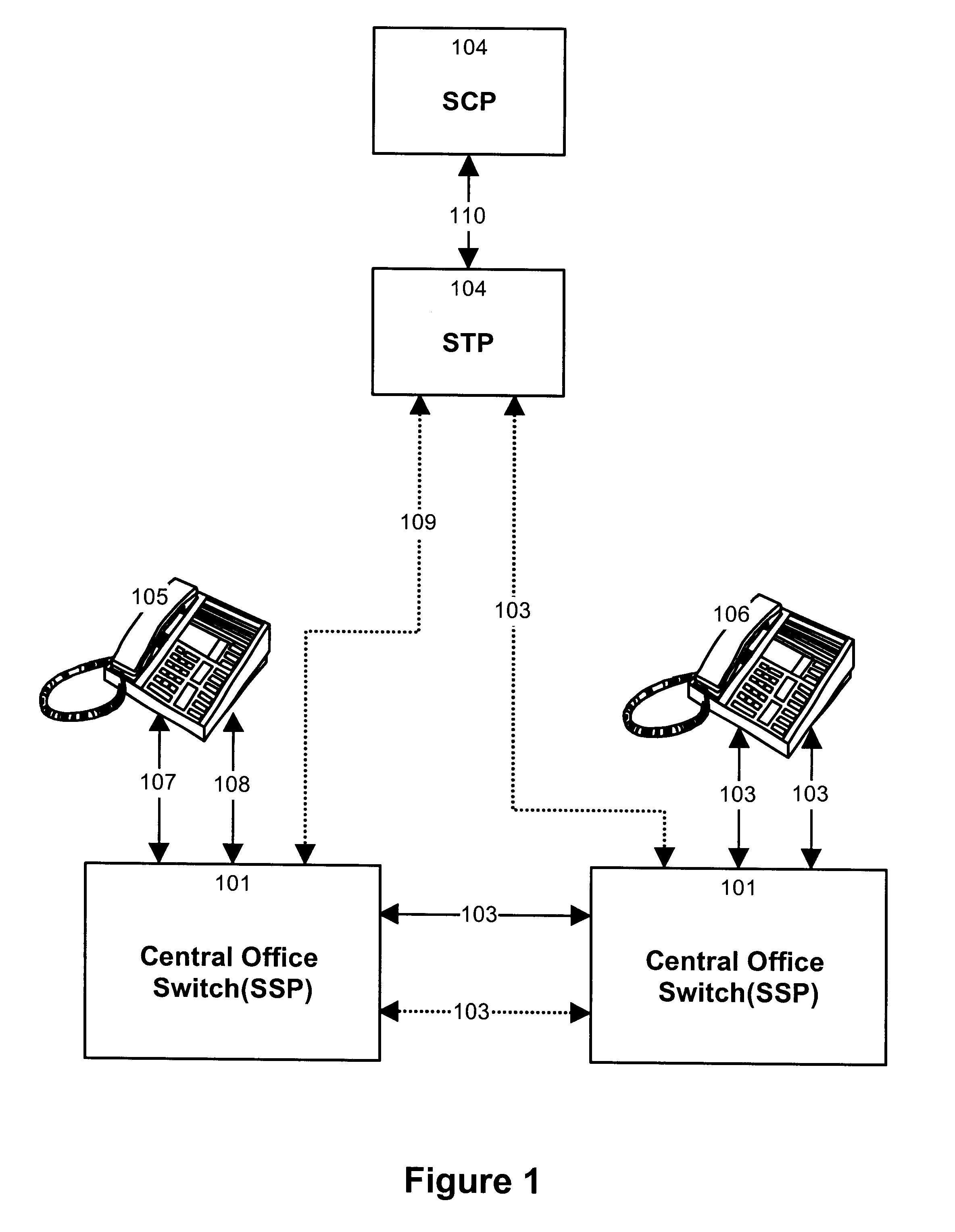
FIG. 1 illustrates schematically the network elements involved in the operation of the invention. That drawing broadly depicts an end-to-end telecommunication system made up of a customer premise equipment (CPE) 105 having an interconnection 107 and 108 to a central office switch 101 located in a public switched telephone network. Interconnections 107 and 108, respectively, identify the voice path channel(s) and data link(s) between the CPE 105 and central office switch 101. Although those interconnections are shown as being separate they may be implemented over the same physical channel.

The central office switch 101 is operational as a service switching point (SSP) which, for AIN processing, means that this switch is set up to detect call processing triggers that invoke intelligent network call processing services. A service control point (SCP) 104 and elements of a common channel signaling system support the AIN operations that are carried out within central offices 101. The eleme...


PUM


Abstract

The invention provides a method and a system for selectively delivering information to callers in an AIN environment. In accordance with the method the service switching point to which is connected the terminal equipment of the caller monitors the condition of the telephone line to detect an AIN trigger, such as an off-hook event among other possibilities. When such event occurs, the service switch point formulates a message query. The query is routed to a service control point via one or more service transfer points, that holds knowledge of the service subscribed by the caller and the information to be displayed for this service. The service control point analyzes the request and assembles the appropriate response. That response is then returned to the service switch point that formats it properly and delivers it to the terminal equipment of the caller. In one embodiment the information delivery is effected during call establishment. In a variant, information is delivered while no call is being attempted.

Description

This invention relates generally to the delivery of information to the caller in the public switched network environment following an AIN trigger processing. The present invention provides a method and a system for coordinating and delivering the information between the public switched network and customer premises equipment (CPE).In prior art, focus has been on the delivery of information to the called party to allow the called party to determine the caller and the nature of the call. For example, public switched telephone networks currently provide the delivery of both name and number to subscribers who have subscribed to this service. The caller can receive the name and / or number information from the public switched network and display the information using appropriate terminal equipment. There is, however, no possibility with currently existing PSTN equipment and protocols to forward back to the calling party messages that provide information relating to the call such as name of...

Claims


Application Information

Patent Timeline
Patent Type & Authority Patents(United States)
IPC IPC(8): H04Q3/00H04M15/28H04M1/57
CPCH04Q3/0029H04M15/28H04M1/57
Inventor TESSLER, MICHAELBELZILE, PIERREMEUBUS, CHARLES
Owner RPX CLEARINGHOUSE
Why Eureka
Try Eureka